• Portfolio
  • Aviation
  • Blog
  • About
Menu

David S Miller

  • Portfolio
  • Aviation
  • Blog
  • About
airfoilGUI_screencap

MATLAB Project: Airfoil Generator

February 19, 2015

I'm taking a class in aerodynamics this semester, and I know we will be working a lot with airfoils. So for fun I decided to write a MATLAB GUI to display any NACA series airfoil. Currently it only works with the 4-series airfoils, but soon I will expand it to work with 5, 6, 7,  8 series airfoils as well.

The program takes inputs of the NACA airfoil number, desired chord length, angle of incidence (AOI), and the wing length. The program then plots each individual airfoil, and lofts the two together in an isometric view. The 'export airfoils' button doesn't work right now, but soon it will export XY coordinates for the airfoils to a text file, so they can be loaded into SolidWorks or another CAD program to make a 3-D model of the wing. 

Download the files to run the program here.

$\setCounter{0}$
In Personal Projects, MATLAB Projects Tags MATLAB, Aircraft Design
Comment
 I missed some photos in the beginning. These are the two jaws of the vise being faced off with a flycutter while bolted together. This was to ensure that the surfaces were parallel and coincident. 

I missed some photos in the beginning. These are the two jaws of the vise being faced off with a flycutter while bolted together. This was to ensure that the surfaces were parallel and coincident. 

 I also had to cut stepper blocks to a certain size in order to ensure the vice clamped the center of the rods.

I also had to cut stepper blocks to a certain size in order to ensure the vice clamped the center of the rods.

 This shows the initial setup. The vise is on the stepper blocks, and parallels are used to ensure the rods are vertical. 

This shows the initial setup. The vise is on the stepper blocks, and parallels are used to ensure the rods are vertical. 

 After tightening the bolts of the vise, I realized the vise was only gripping the two largest dowels. So I cut a piece of rubber to fit in between one of the vise jaws and the dowels to better distribute the pressure amongst the dowels. 

After tightening the bolts of the vise, I realized the vise was only gripping the two largest dowels. So I cut a piece of rubber to fit in between one of the vise jaws and the dowels to better distribute the pressure amongst the dowels. 

IMG_6001.jpg
 The first machining test. You can see the tops of the rods were clamped together using parallels. This helped a lot to reduce the variability. 

The first machining test. You can see the tops of the rods were clamped together using parallels. This helped a lot to reduce the variability. 

 I used even taller parallels the second time, to reduce the variability more. This run had pretty consistent results. I just wish we had an endmill that was smaller than 1/8". 

I used even taller parallels the second time, to reduce the variability more. This run had pretty consistent results. I just wish we had an endmill that was smaller than 1/8". 

 I missed some photos in the beginning. These are the two jaws of the vise being faced off with a flycutter while bolted together. This was to ensure that the surfaces were parallel and coincident.   I also had to cut stepper blocks to a certain size in order to ensure the vice clamped the center of the rods.  This shows the initial setup. The vise is on the stepper blocks, and parallels are used to ensure the rods are vertical.   After tightening the bolts of the vise, I realized the vise was only gripping the two largest dowels. So I cut a piece of rubber to fit in between one of the vise jaws and the dowels to better distribute the pressure amongst the dowels.  IMG_6001.jpg  The first machining test. You can see the tops of the rods were clamped together using parallels. This helped a lot to reduce the variability.   I used even taller parallels the second time, to reduce the variability more. This run had pretty consistent results. I just wish we had an endmill that was smaller than 1/8". 

Mini Project: Tooling/Fixturing for Tensegrity Rods

February 3, 2015

Part of my job as an engineering education developer includes designing and manufacturing the parts needed for the activities. One of the activities I helped create was on the structural design principle of tensegrity. Tensegrity is a way to build structures that are lightweight and strong. They rely on flexible tensile elements such as strings, ropes, or cables; as well as on stiff compressional elements such as rods. Tensegrity structures are pre-stressed and self stabilizing, and none of the compressional members touch. They are suspended in a web of tensional elements, a phenomenon referred to as "floating compression" by artist Kenneth Snelson. 

The activity itself is like a board game to teach students the entrepreneurial aspects of engineering. The activity centers around building a mini tensegrity tower. These towers use wooden dowels with notches cut in either end; rubber bands fit in these notches and hold the rods together in a simple tensegrity structure. The problem is that the balance and symmetry of the tower depends on the quality of the rods. All the rods must be made to a high standard, or else the tensegrity towers become very asymmetrical and unstable. This is because with different length rods, the rubber bands are stretched to different lengths and therefore exert different restoring forces. The imbalance of restorative forces within the structure causes the structure to shift in order to find a new equilibrium. This throws everything off. 

To make the towers as balanced as possible, a manufacturing method was needed to produce the rods very quickly and precisely. I decided to make a simple vise to hold the rods. The vise is clamped into the vise of a mill, which can be used to machine the notches on one end. Then, the inner vise can be flipped upside down to machine the other side of the rods. 

There were a few caveats to this approach; the length of the rods compared to the size of the vise made it difficult to clamp into the mill's vise jaws. Additionally, the length of the dowels sticking out of the vise made it difficult to machine cleanly without using extra clamps to restrict the motion. All in all, however, it worked pretty well and I think these towers will perform much better.

$\setCounter{0}$
In Engineering Education, Machining Projects
Comment
 Original sketch of concept

Original sketch of concept

 More detailed sketches of the parts. I ended up changing most of the dimensions.

More detailed sketches of the parts. I ended up changing most of the dimensions.

 Open Position

Open Position

 Closed Position

Closed Position

 30˚!

30˚!

 Threads won't go that deep in the hole... Gotta make the hole deeper.

Threads won't go that deep in the hole... Gotta make the hole deeper.

 Original sketch of concept  More detailed sketches of the parts. I ended up changing most of the dimensions.  Open Position  Closed Position  30˚!  Threads won't go that deep in the hole... Gotta make the hole deeper.

Project: Drafting Bars

January 20, 2015

Engineers convey ideas through drawings and sketches. When sketching rectangular objects in orthographic or isometric views, it is necessary to be able to draw parallel lines. Additionally, for isometric views, the lines are offset 30˚ from the horizontal. I wanted to make a tool that would help me draw parallel lines and 30˚ angles to be able to make sketches quicker and more accurately.

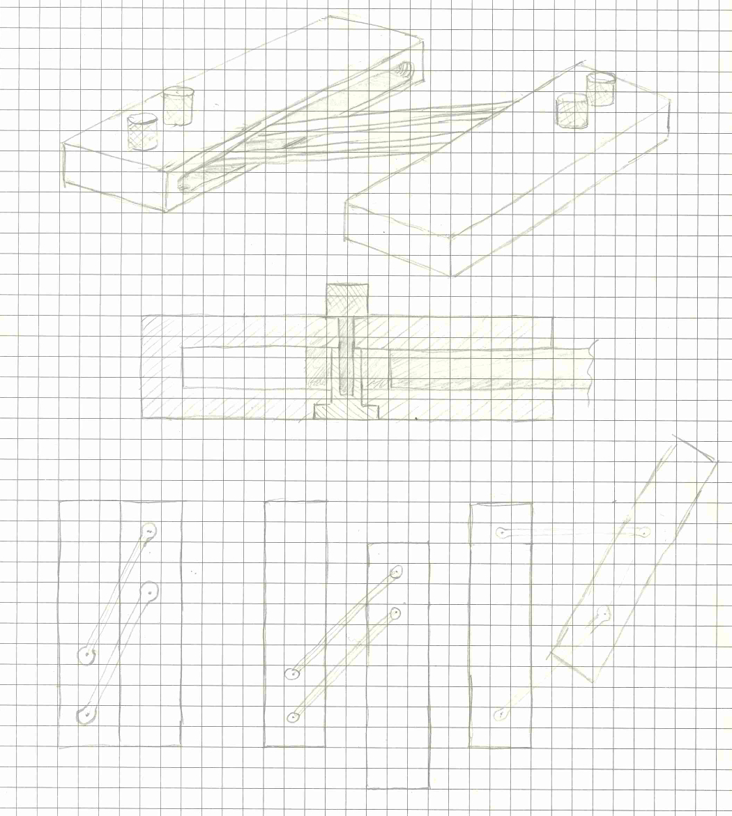
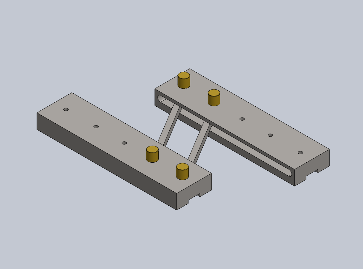
My initial conceptual idea was to have two bars connected by two rods to form a parallelogram linkage. This way, one bar could 'follow' the original line, while the other [parallel] bar could be extended and a parallel line could be traced along the edge of the bar at any desired distance. 

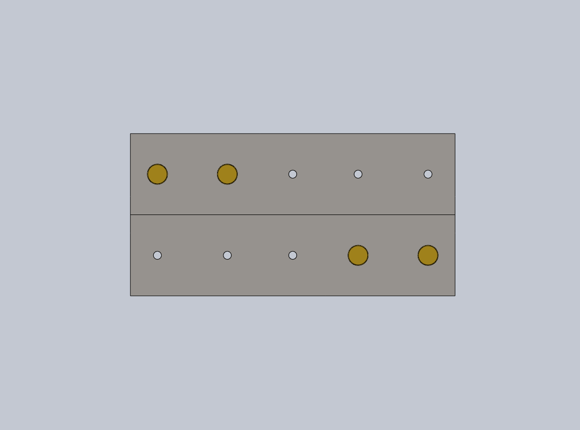
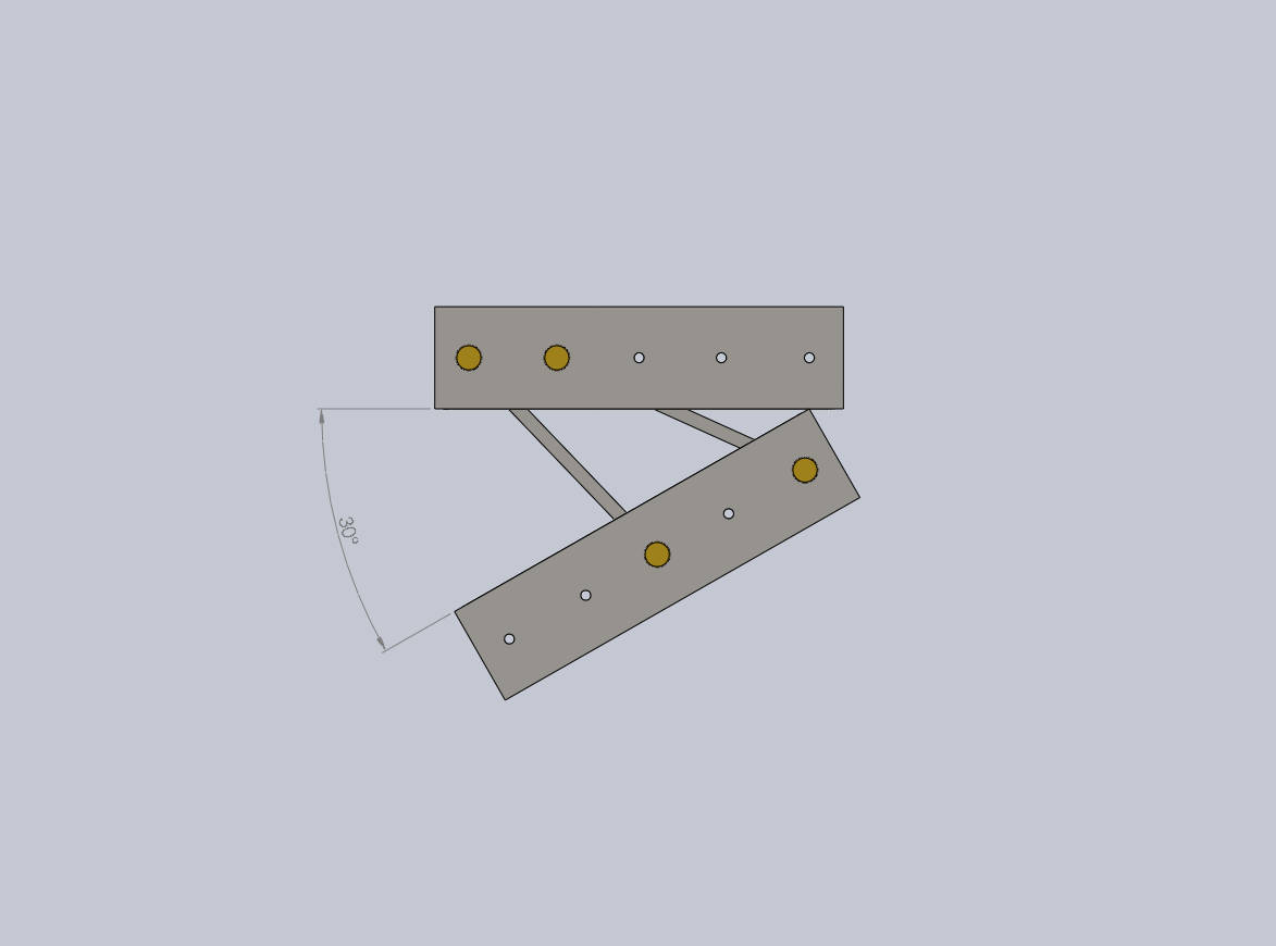
Making the 30˚ angle was more tricky. My original thought was to have different sized rods that could be swapped out to make different angles, but I thought there was probably a simpler and more elegant way to do it. I eventually decided to add extra holes as alternate positions for the rods. In their alternate positions the rods are no longer parallel, and thus the angle between the bars can change. The freedom of motion of the bars is limited by their interference, and so by adjusting the geometries of the parts, a 30˚ can be obtained when the bars are touching each other. 

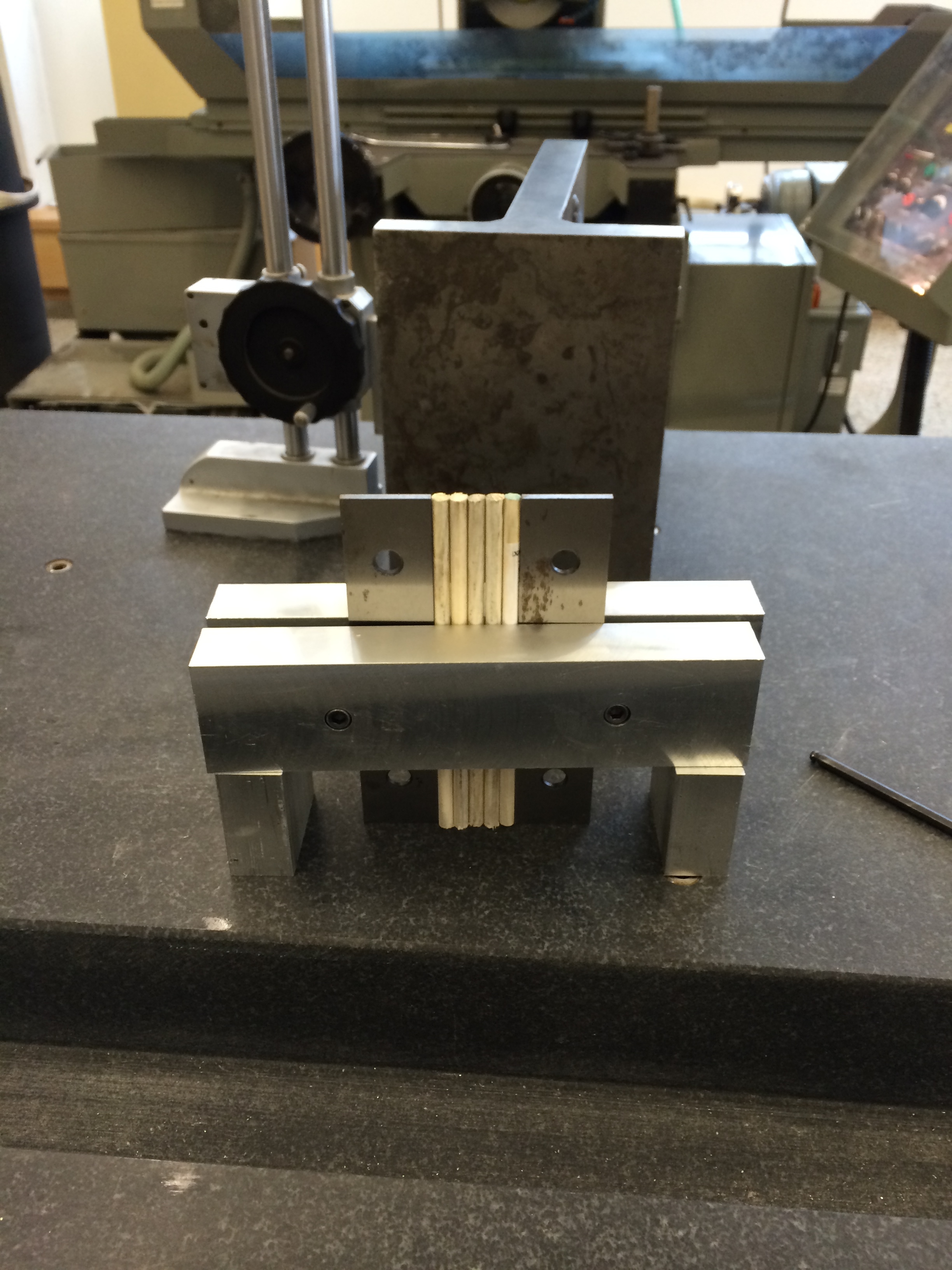
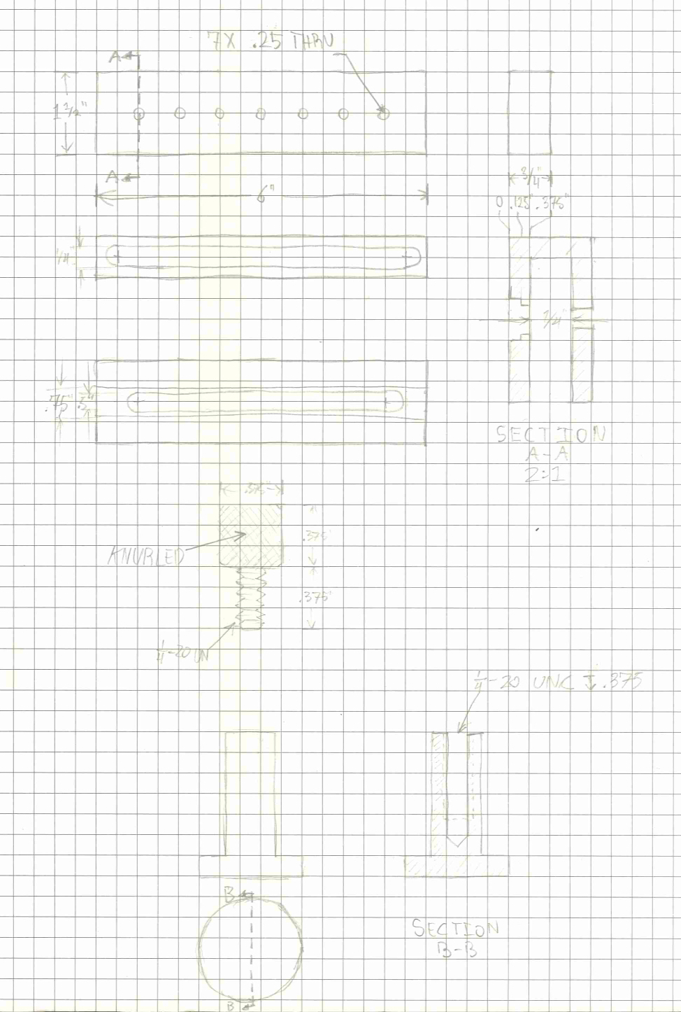
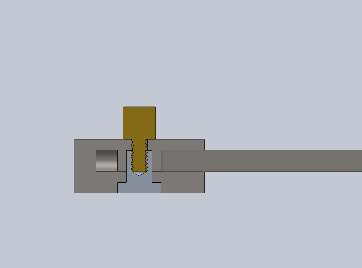
The last element of the design was how all the pieces fit together. I decided to use knurled brass knobs that threaded into a nut. The nut head fits into a channel, and the shank of the nut slides in a slot. The rod end fits around the nut, and the length of the rod is contained within a pocket in the bar. Tightening the knob presses the bar against the rod to lock it in place. If the knob is unscrewed completely, the rod end can be moved to a different hole to get the 30˚ angle.

This is the first version of the design. I'm still not sure what materials to use for the different parts. I really like the look of knurled brass knobs and rods, but I'll need to make sure they are strong enough. I originally planned to use 304 Stainless Steel for the bars for longevity and cost, but the locking function depends on the the ability of the bar to deflect under the force of the knob and press against the rod. 


$\setCounter{0}$
In Personal Projects, Machining Projects Tags Machining
Comment
← Newer Posts

Blogpost Search

Blogposts by Category

Select Category
  • Academic Projects
  • Aviation
  • BreakerBot
  • Engineering Education
  • Illusionist's Locket
  • MATLAB Projects
  • Machining Projects
  • Personal Projects

Archive

  • May 2024
  • December 2019
  • November 2019
  • September 2019
  • April 2017
  • January 2017
  • August 2016
  • May 2016
  • April 2016
  • March 2016
  • February 2016
  • January 2016
  • November 2015
  • October 2015
  • June 2015
  • April 2015
  • February 2015
  • January 2015

Copyright © David Miller 2019