• Portfolio
  • Aviation
  • Blog
  • About
Menu

David S Miller

  • Portfolio
  • Aviation
  • Blog
  • About
 The barrel superglued into the groove

The barrel superglued into the groove

 Sonia holding her handiwork. I walked her through everything, but she manipulated all the handles and levers herself!

Sonia holding her handiwork. I walked her through everything, but she manipulated all the handles and levers herself!

 For safety's sake I used the torch to release the superglue bond

For safety's sake I used the torch to release the superglue bond

IMG_7533.JPG
 Comparing the size of the punch to the size of the hole where the photo will go. It's quite a snug fit. 

Comparing the size of the punch to the size of the hole where the photo will go. It's quite a snug fit. 

 We lasercut another couple of hooks for the robot as that is the part that is most likely to break during transport.

We lasercut another couple of hooks for the robot as that is the part that is most likely to break during transport.

 Sonia holding the BreakerBot!

Sonia holding the BreakerBot!

 The barrel superglued into the groove  Sonia holding her handiwork. I walked her through everything, but she manipulated all the handles and levers herself!  For safety's sake I used the torch to release the superglue bond IMG_7533.JPG  Comparing the size of the punch to the size of the hole where the photo will go. It's quite a snug fit.   We lasercut another couple of hooks for the robot as that is the part that is most likely to break during transport.  Sonia holding the BreakerBot!

Illusionist's Heart Locket Pt. 7

May 16, 2016

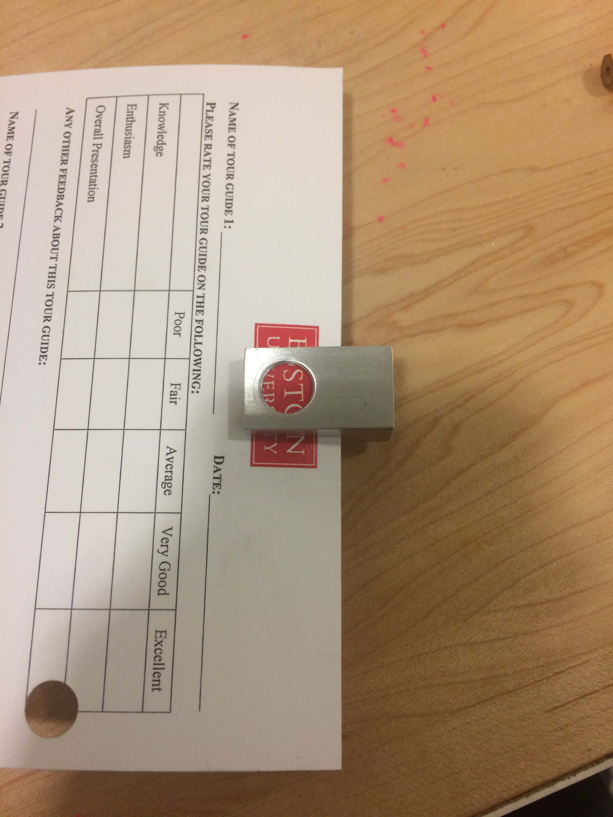
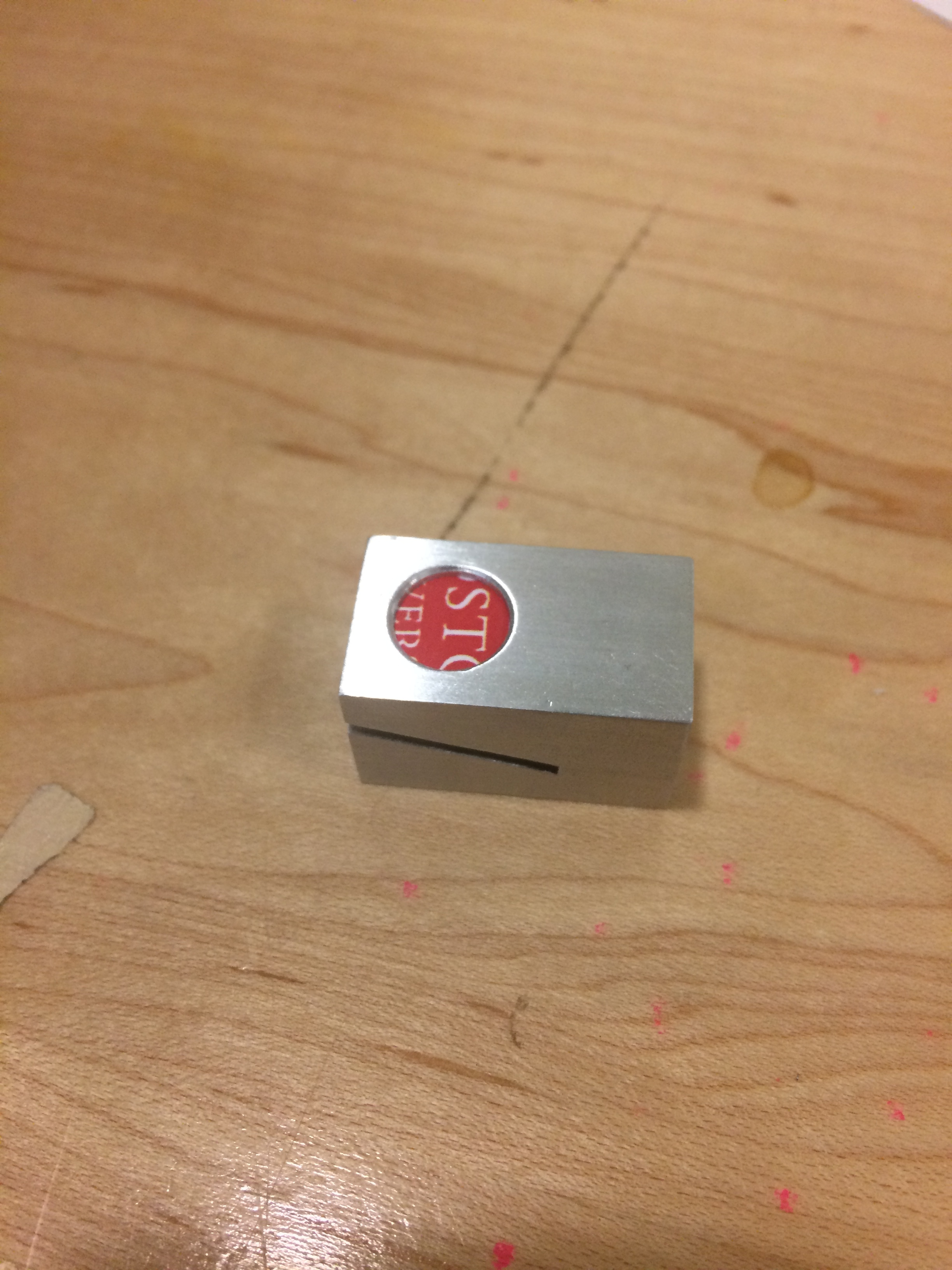
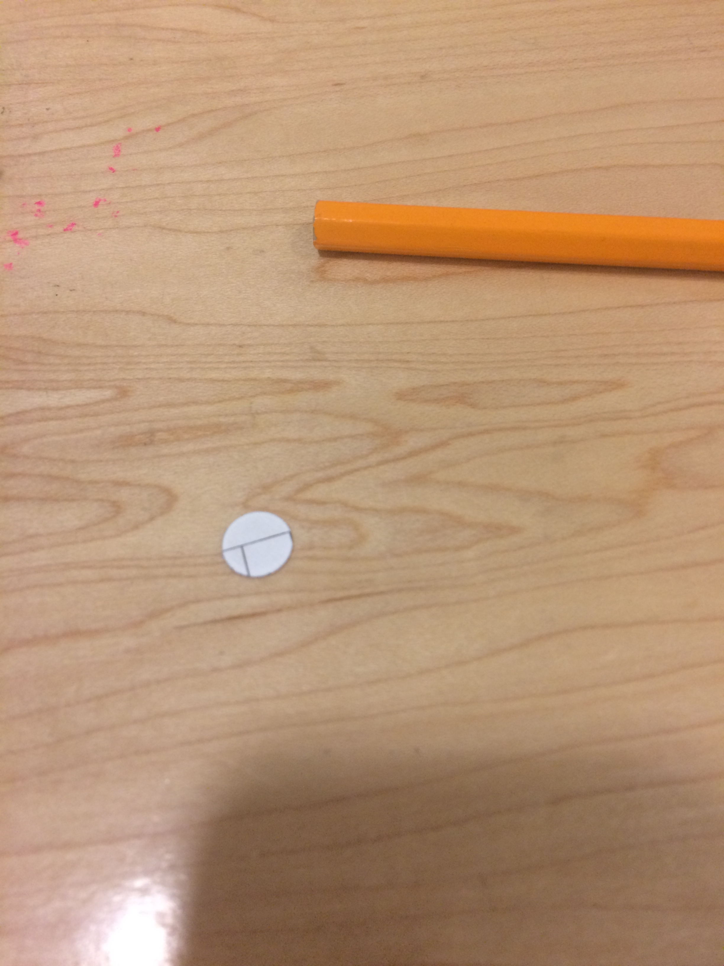
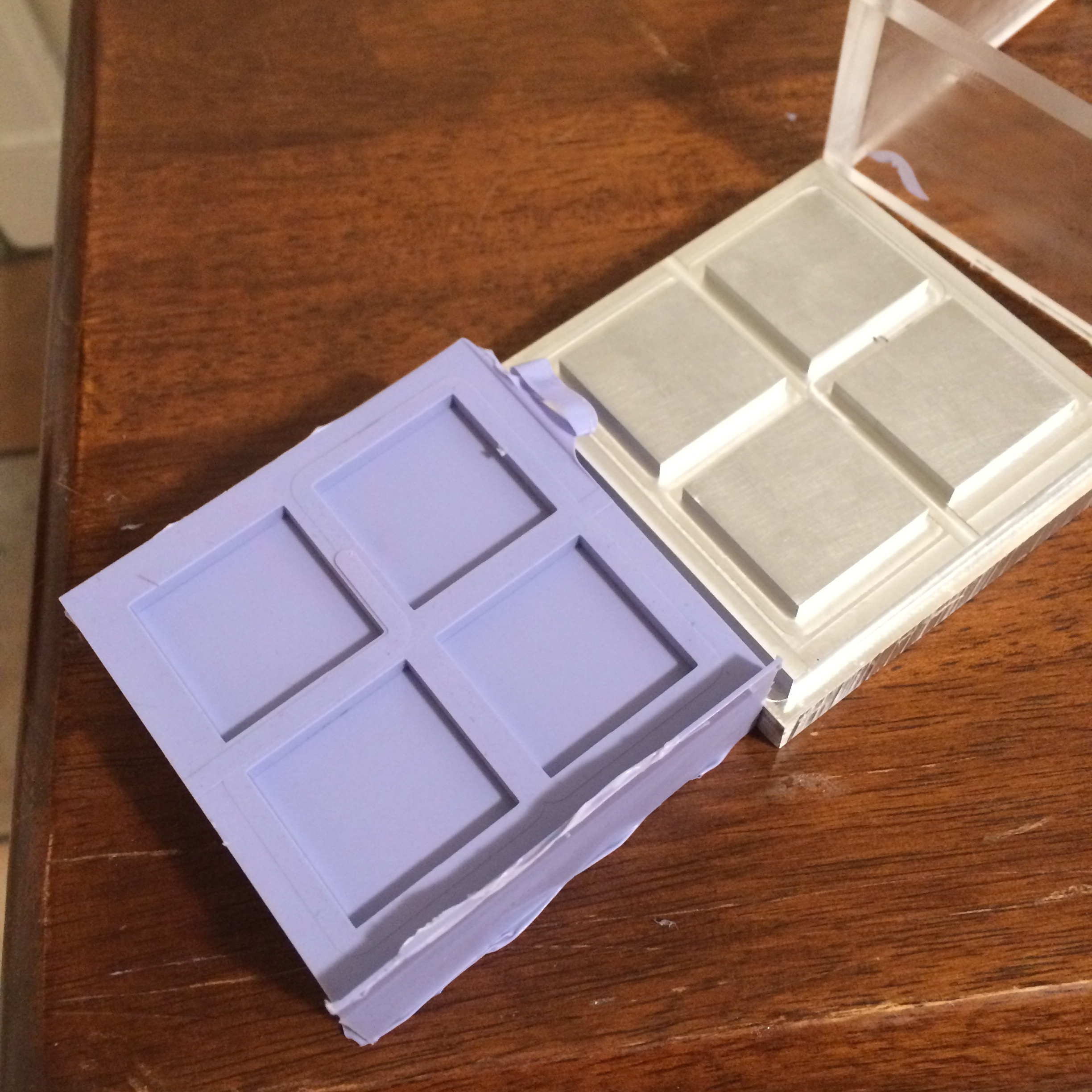
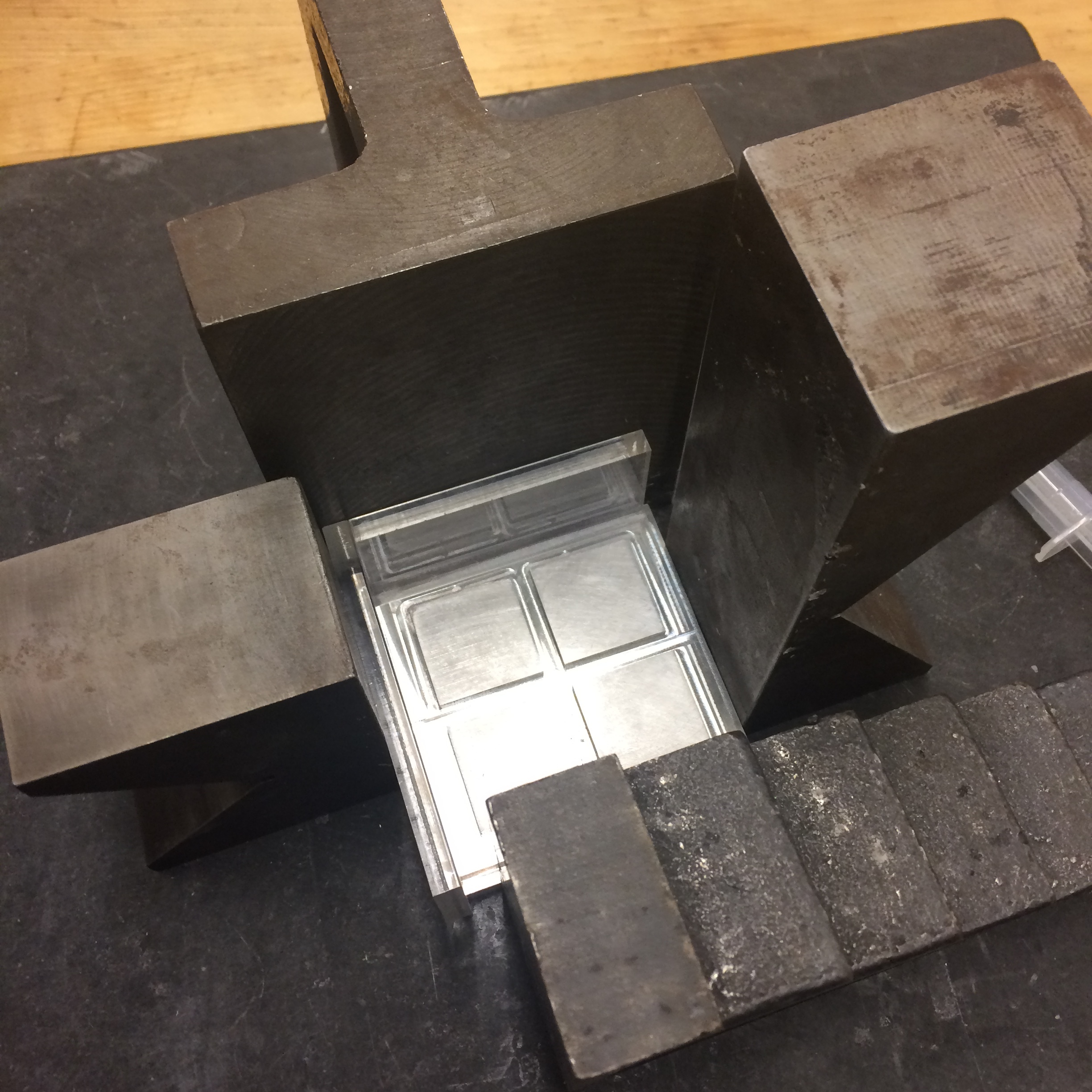
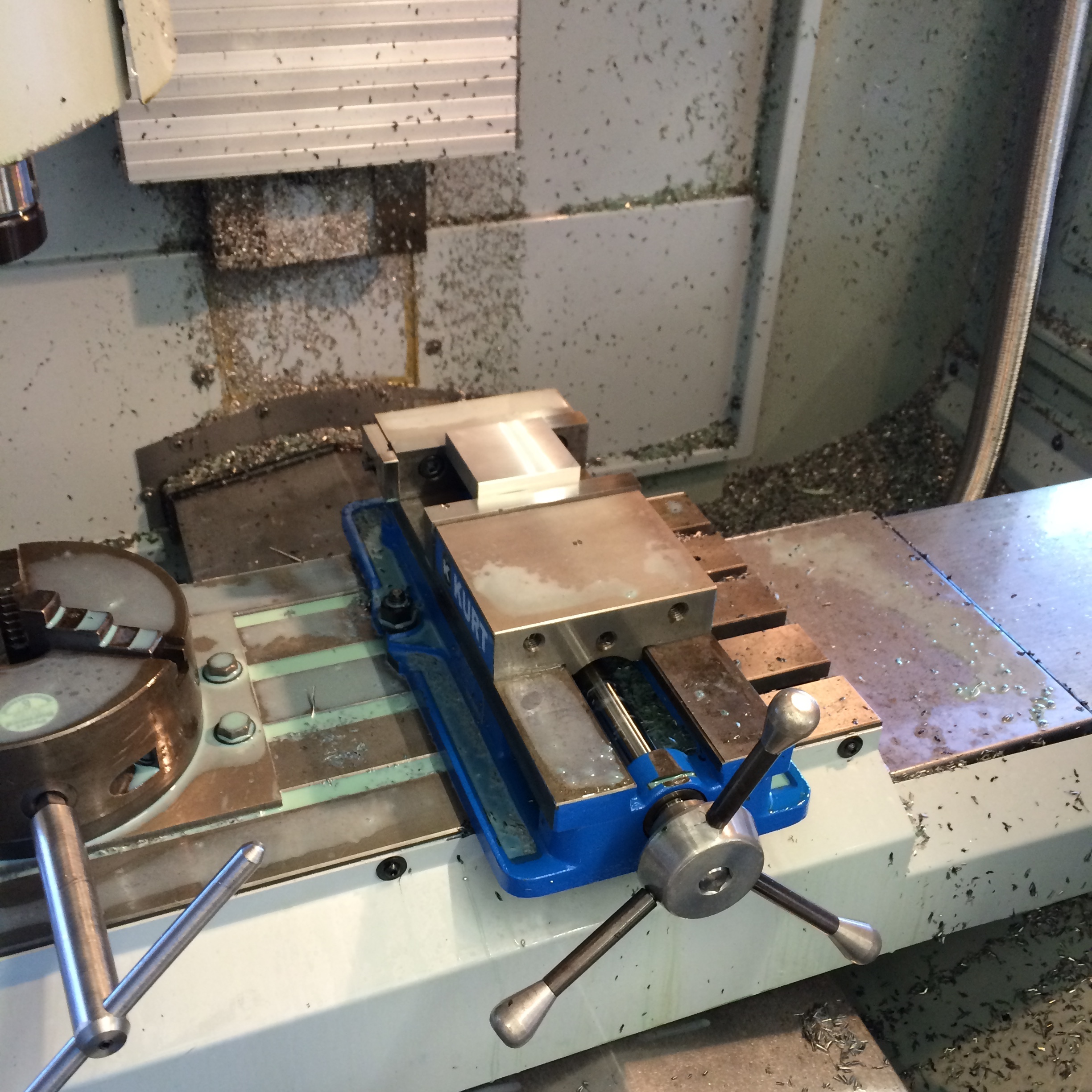
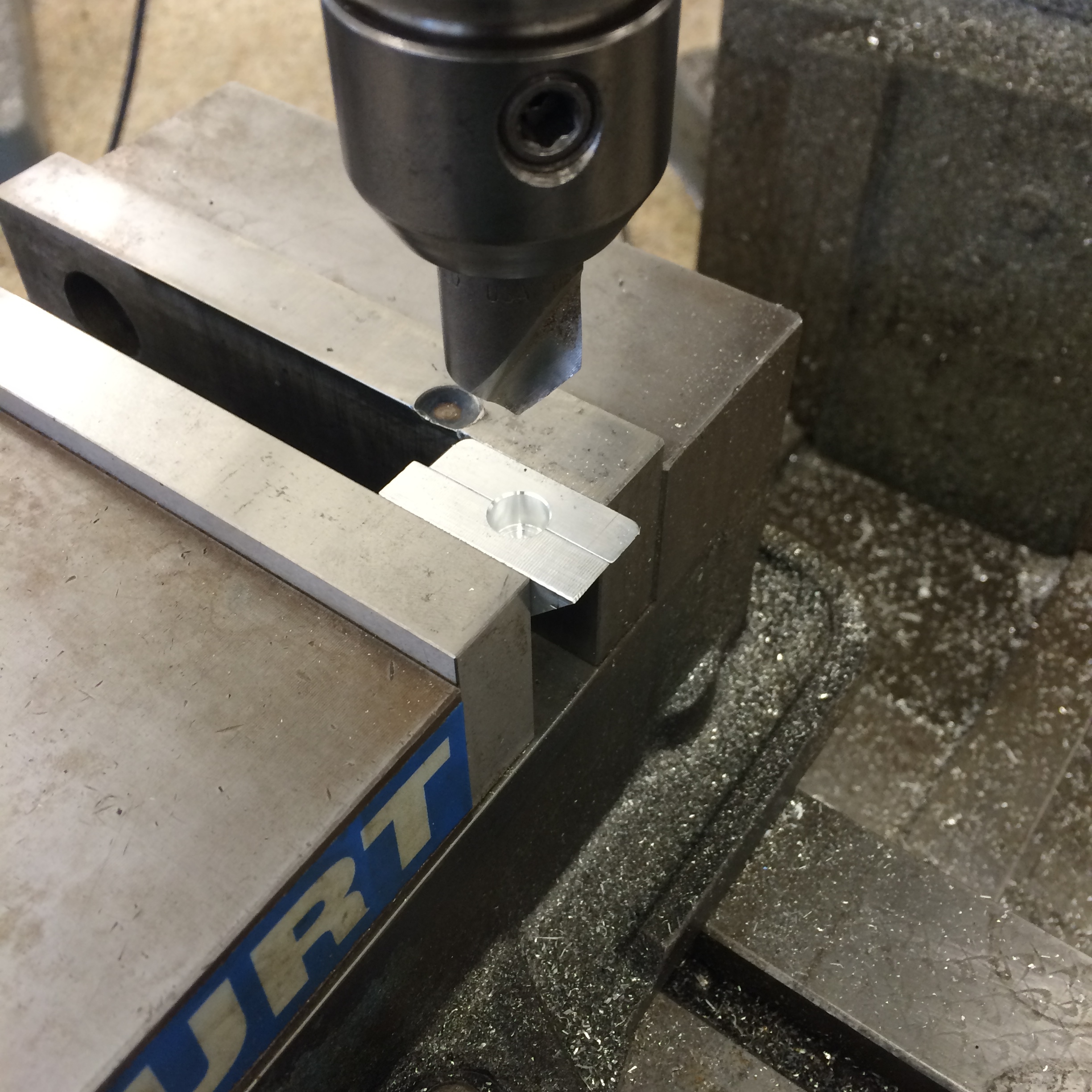
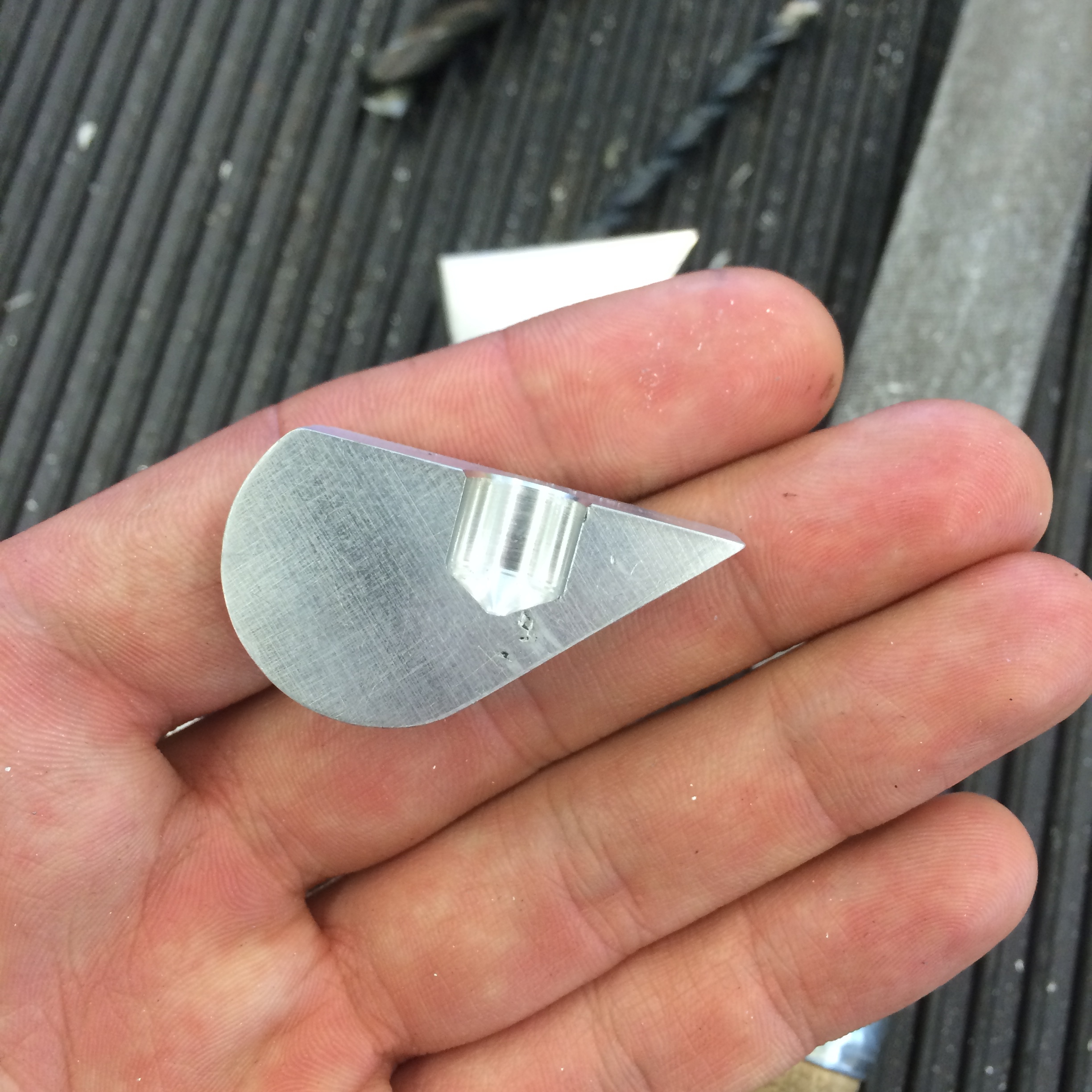
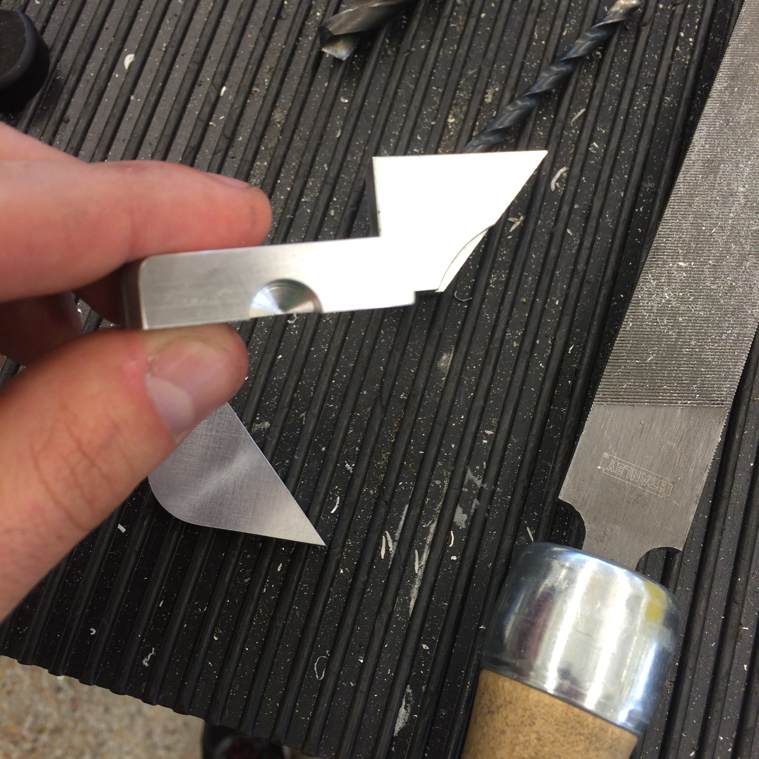
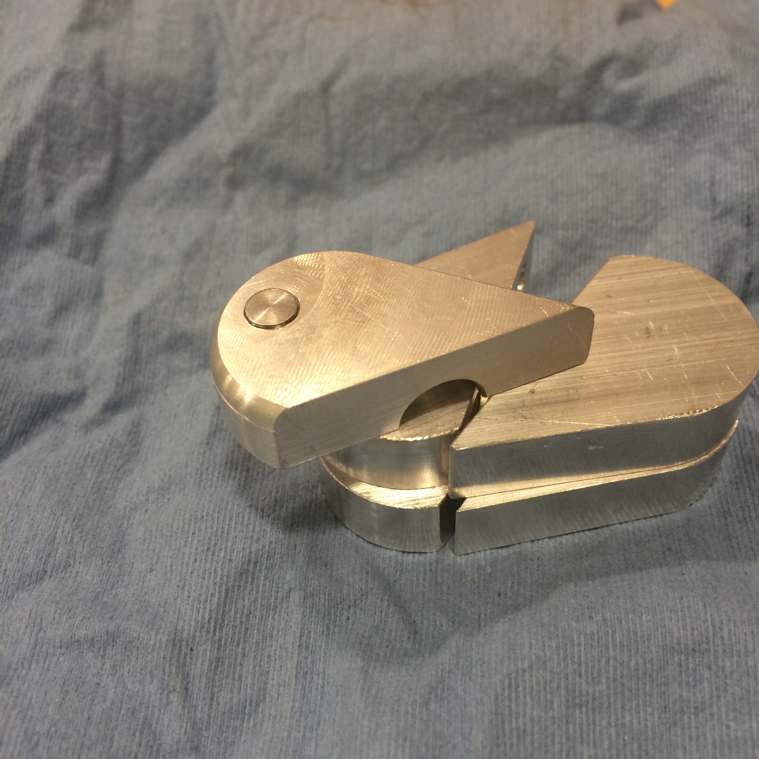
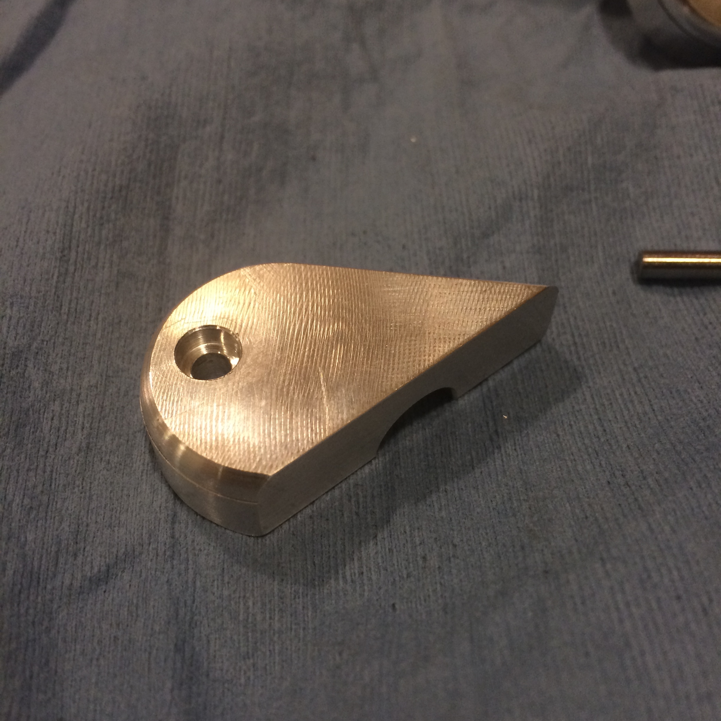
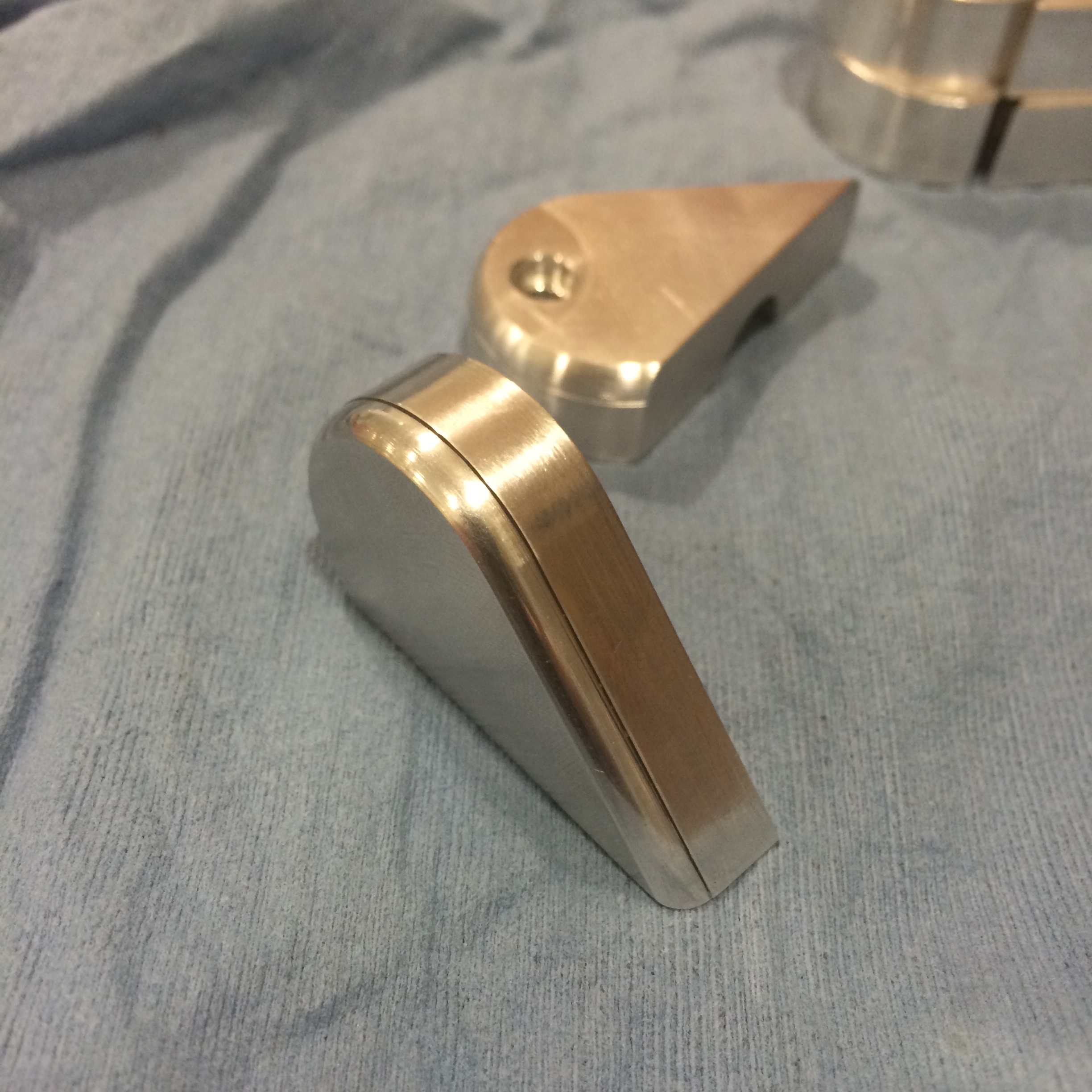
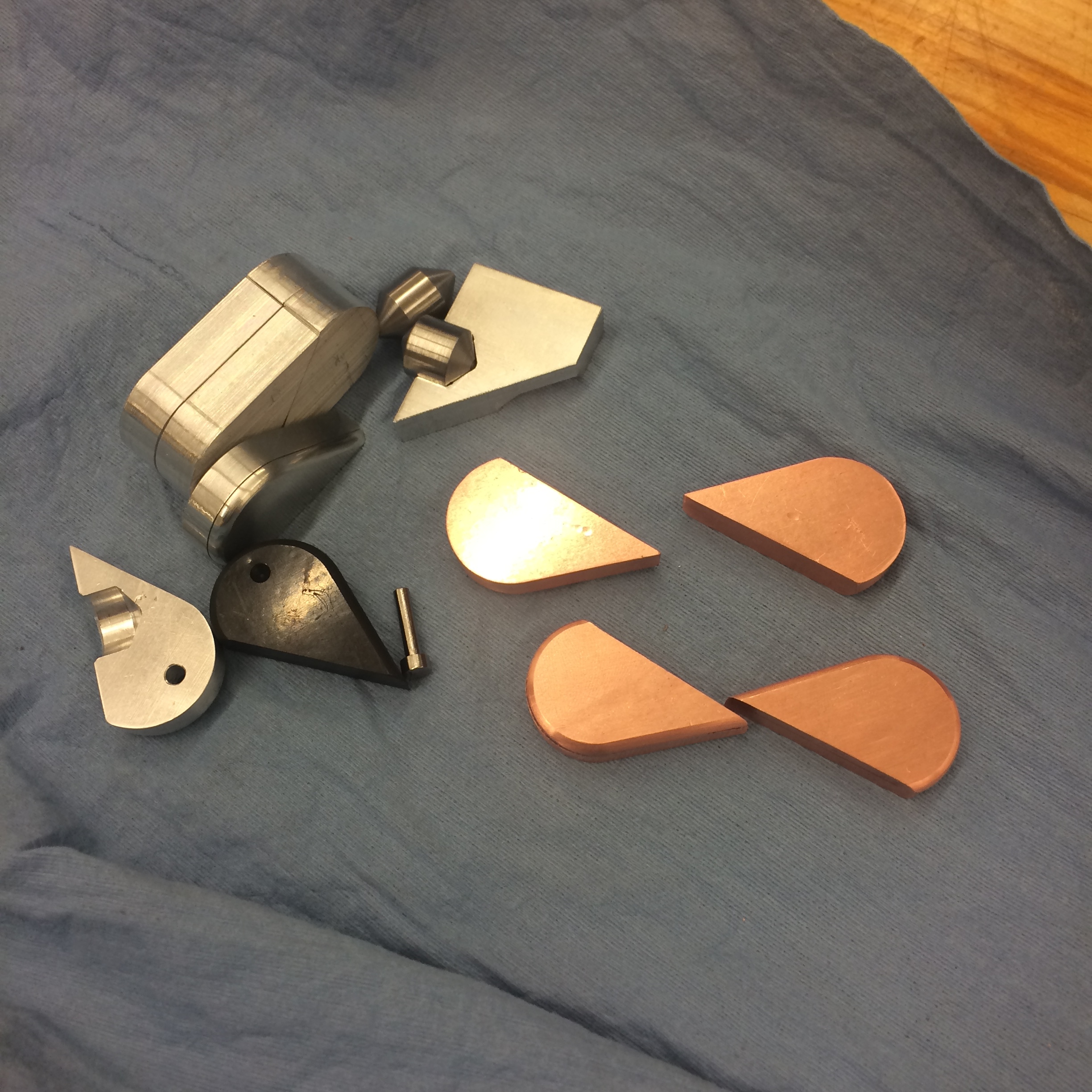
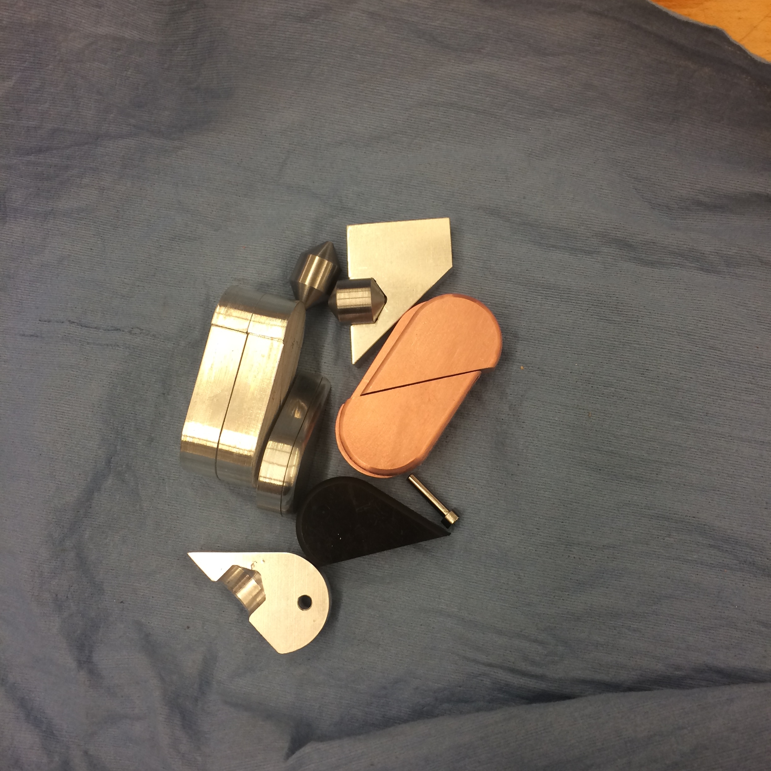
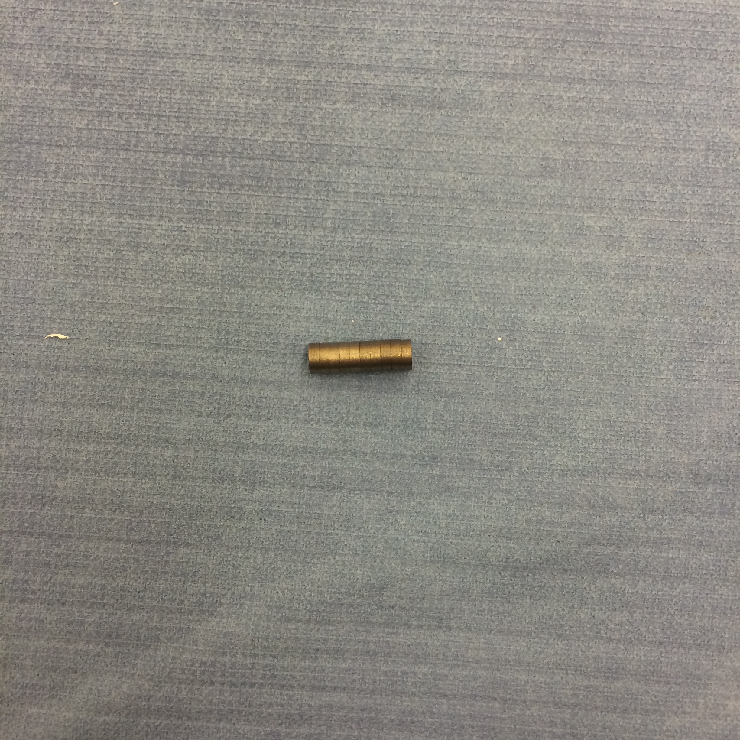
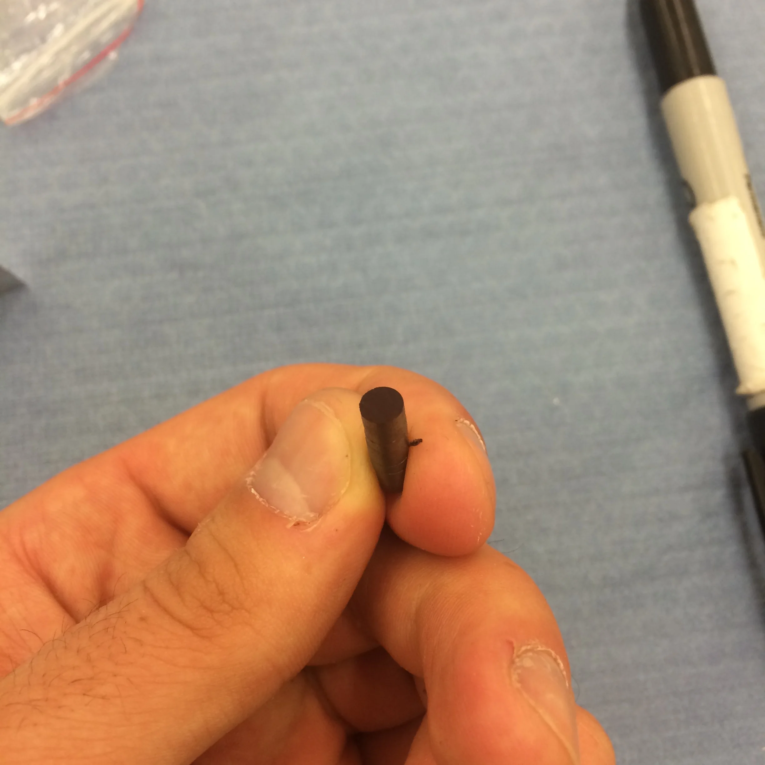
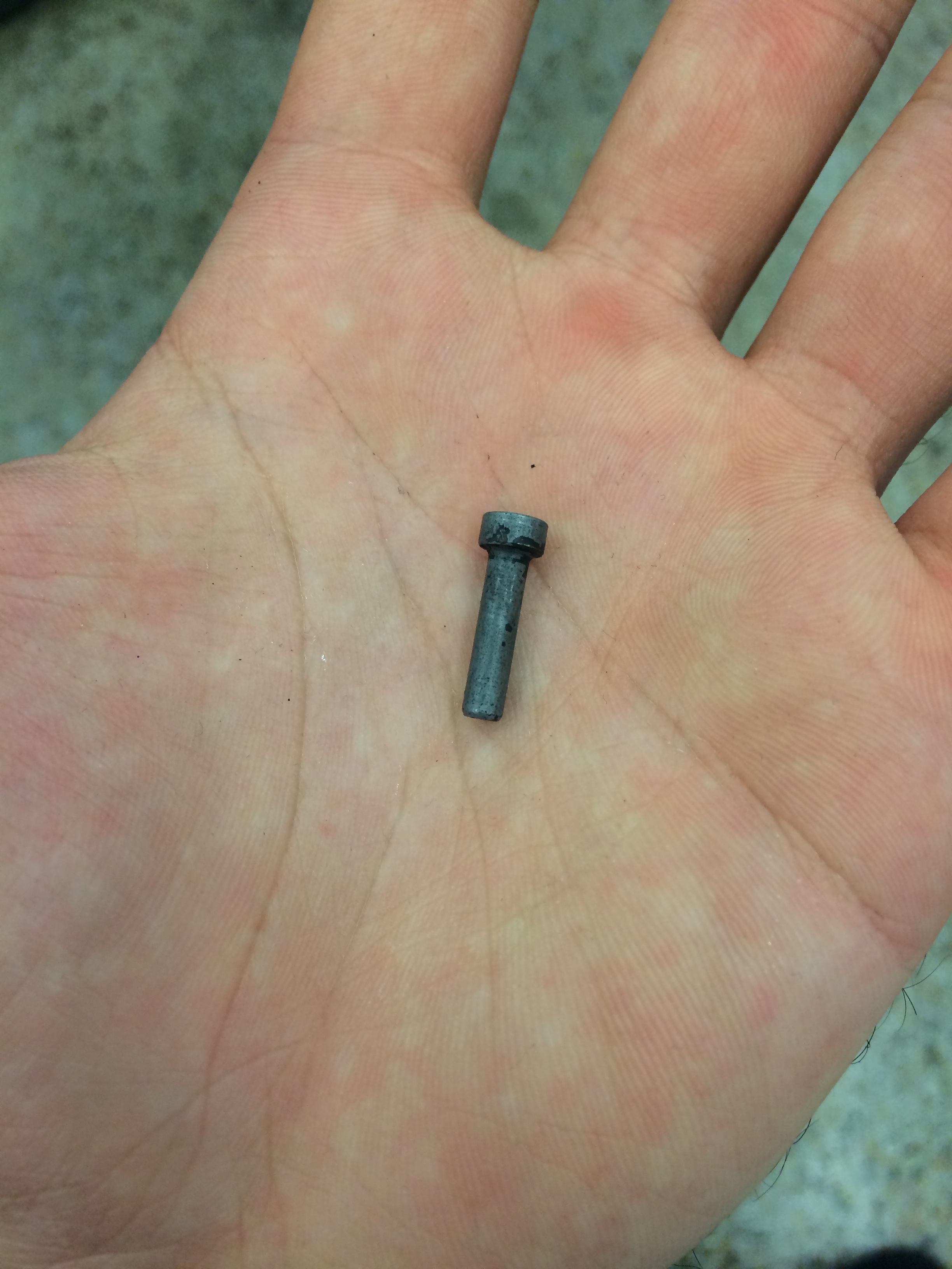
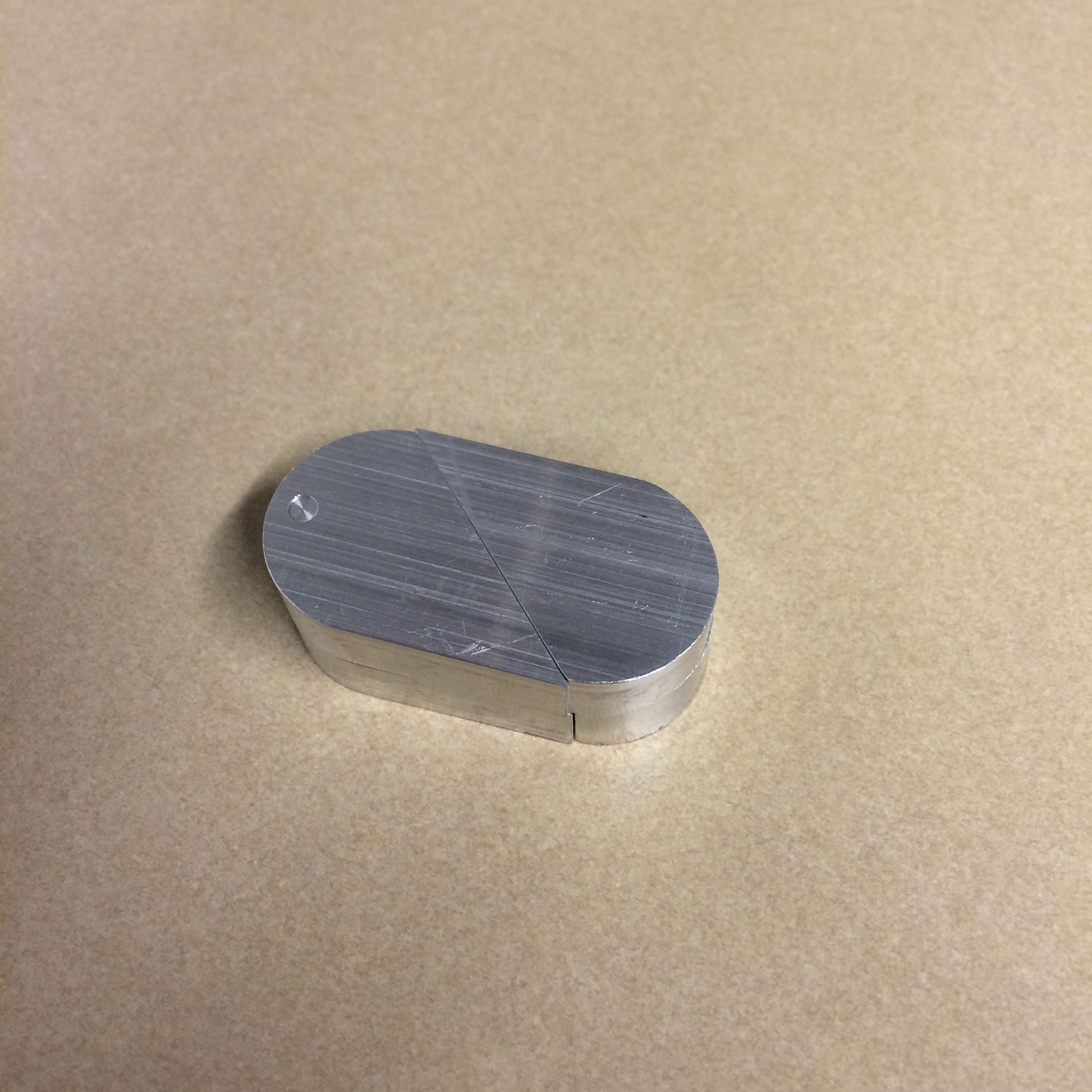
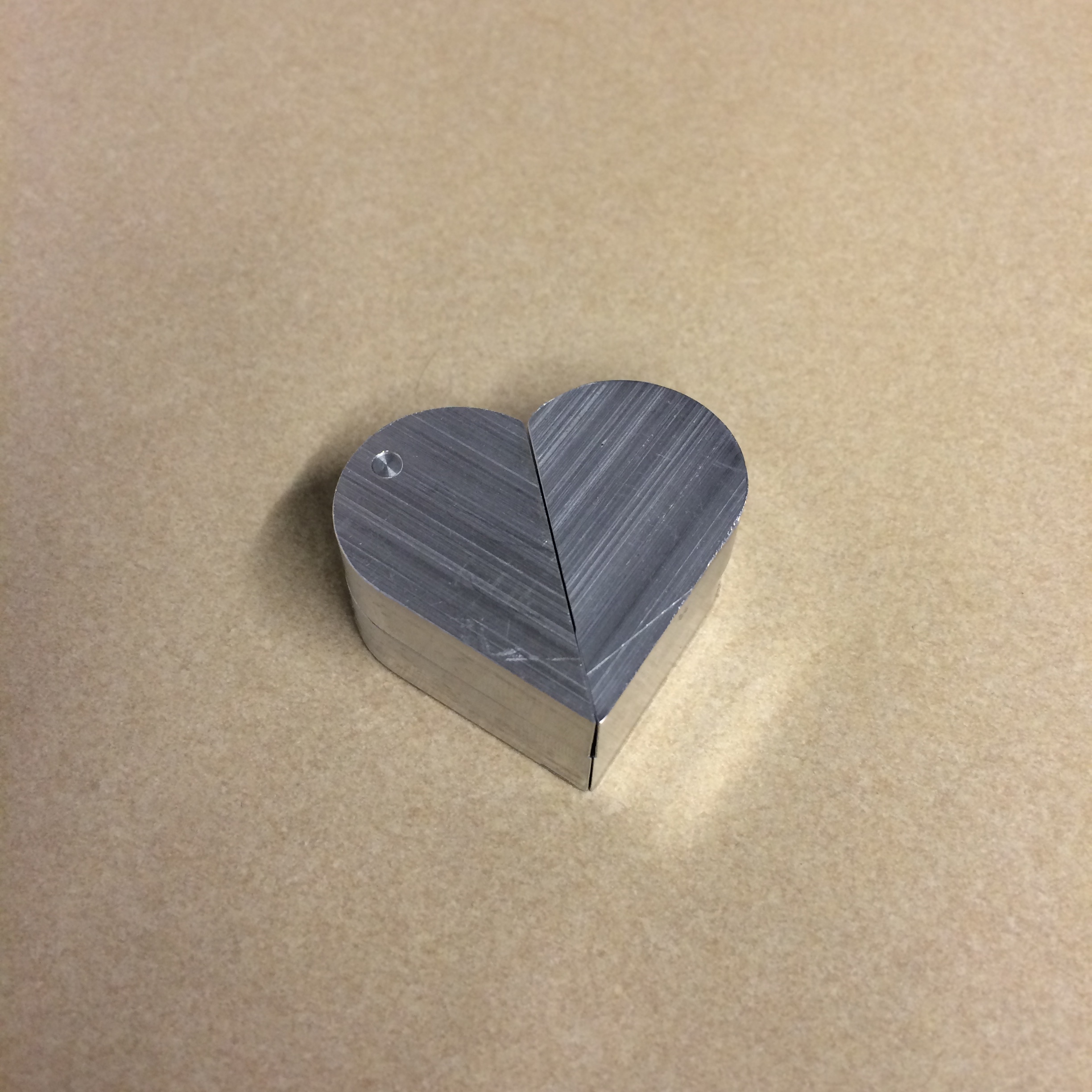
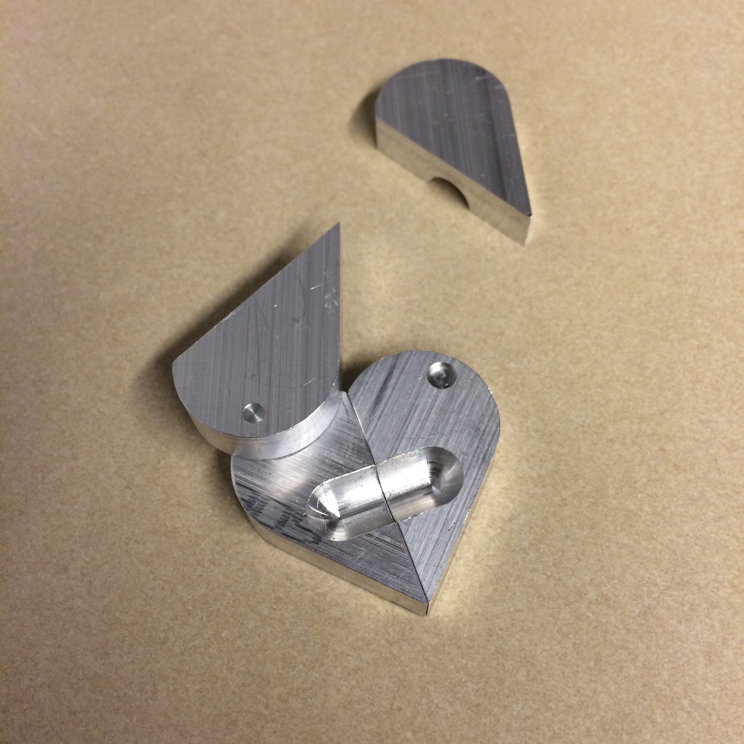
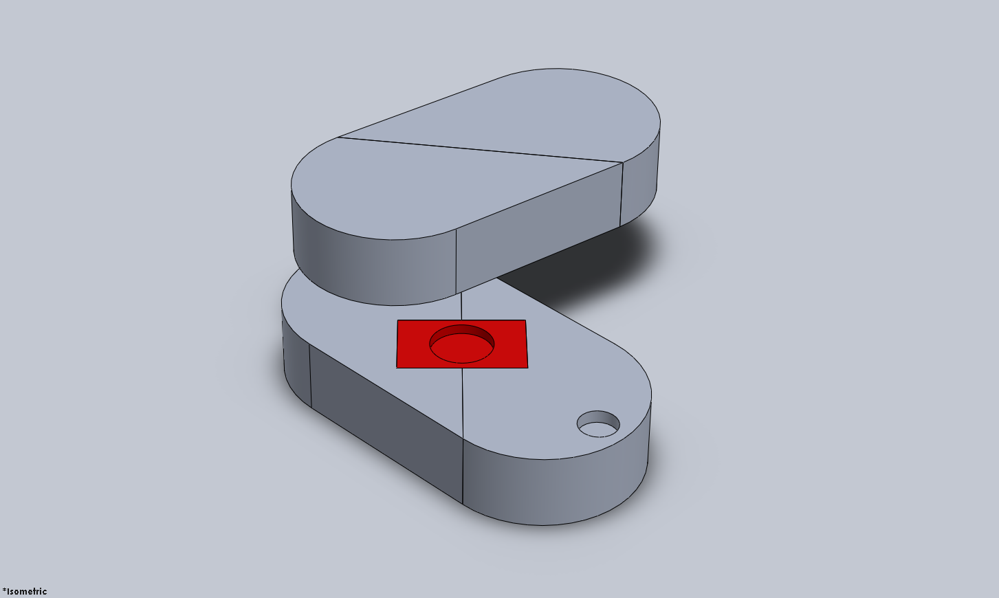
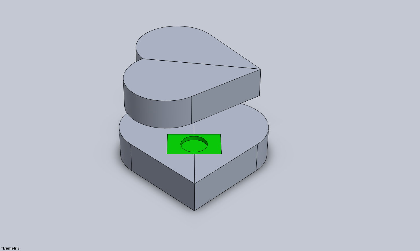
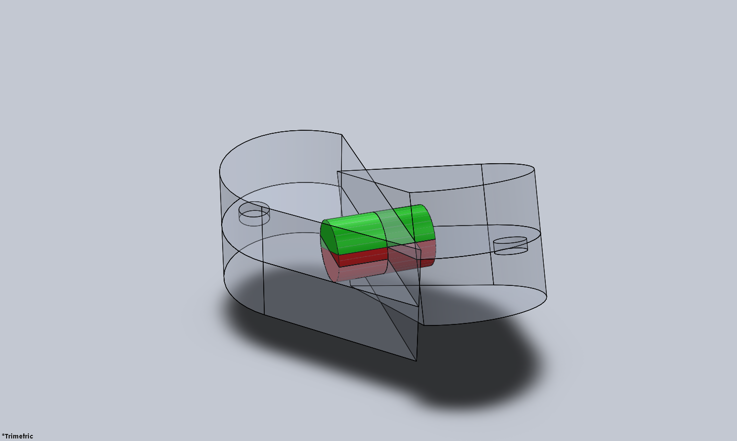
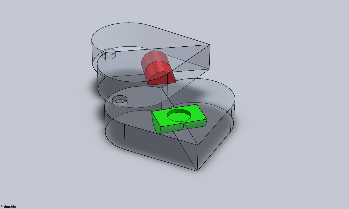
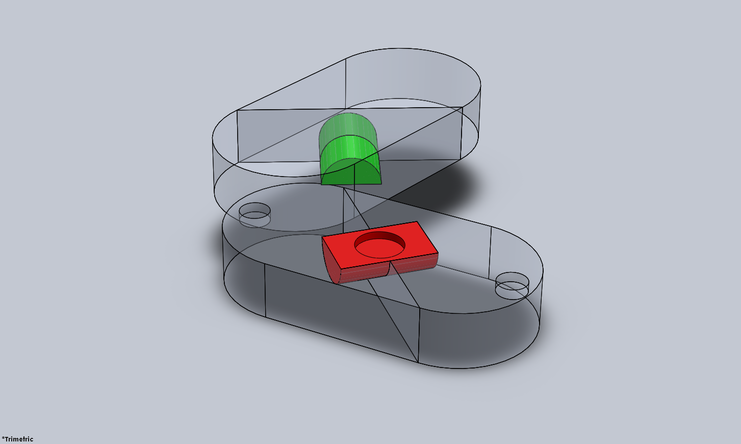
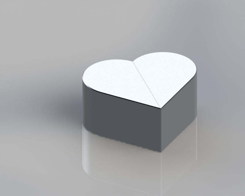
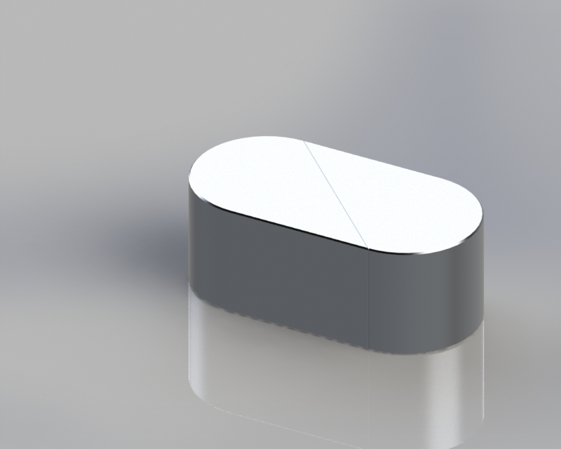
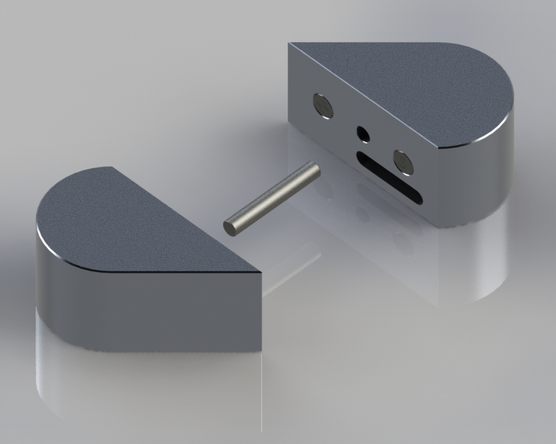
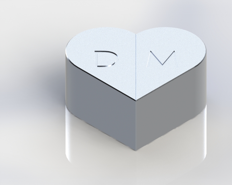
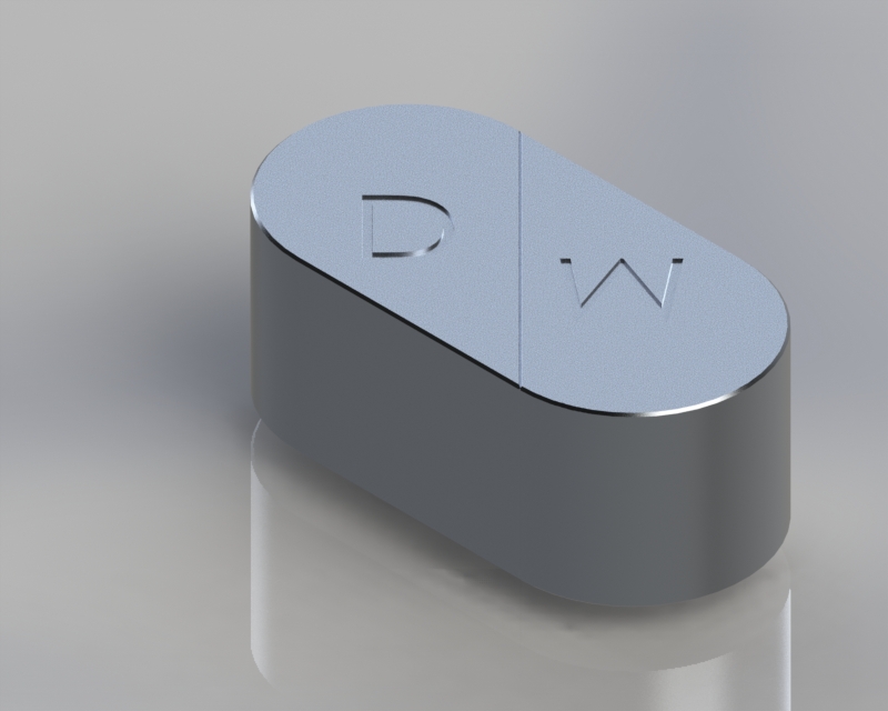
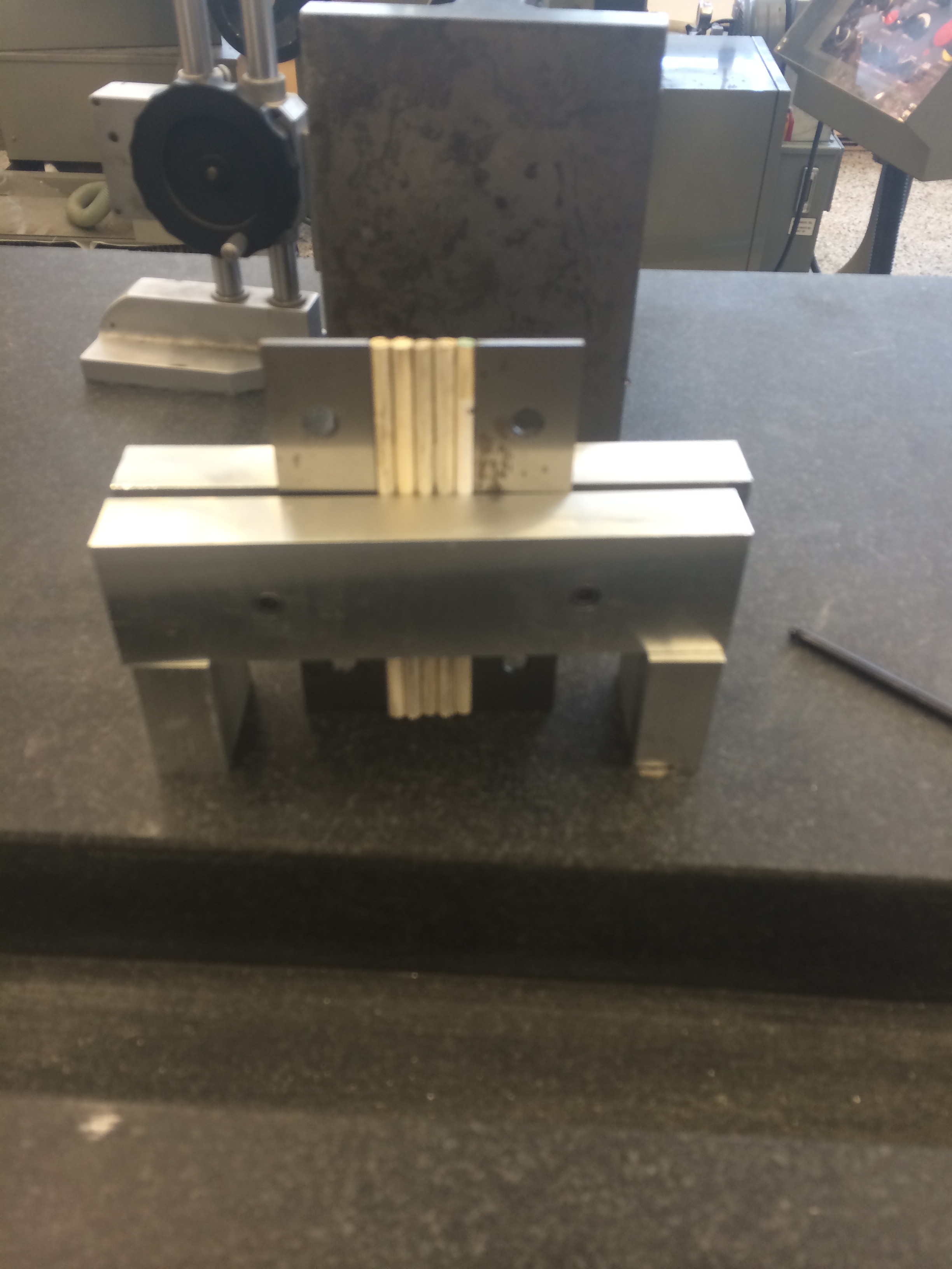
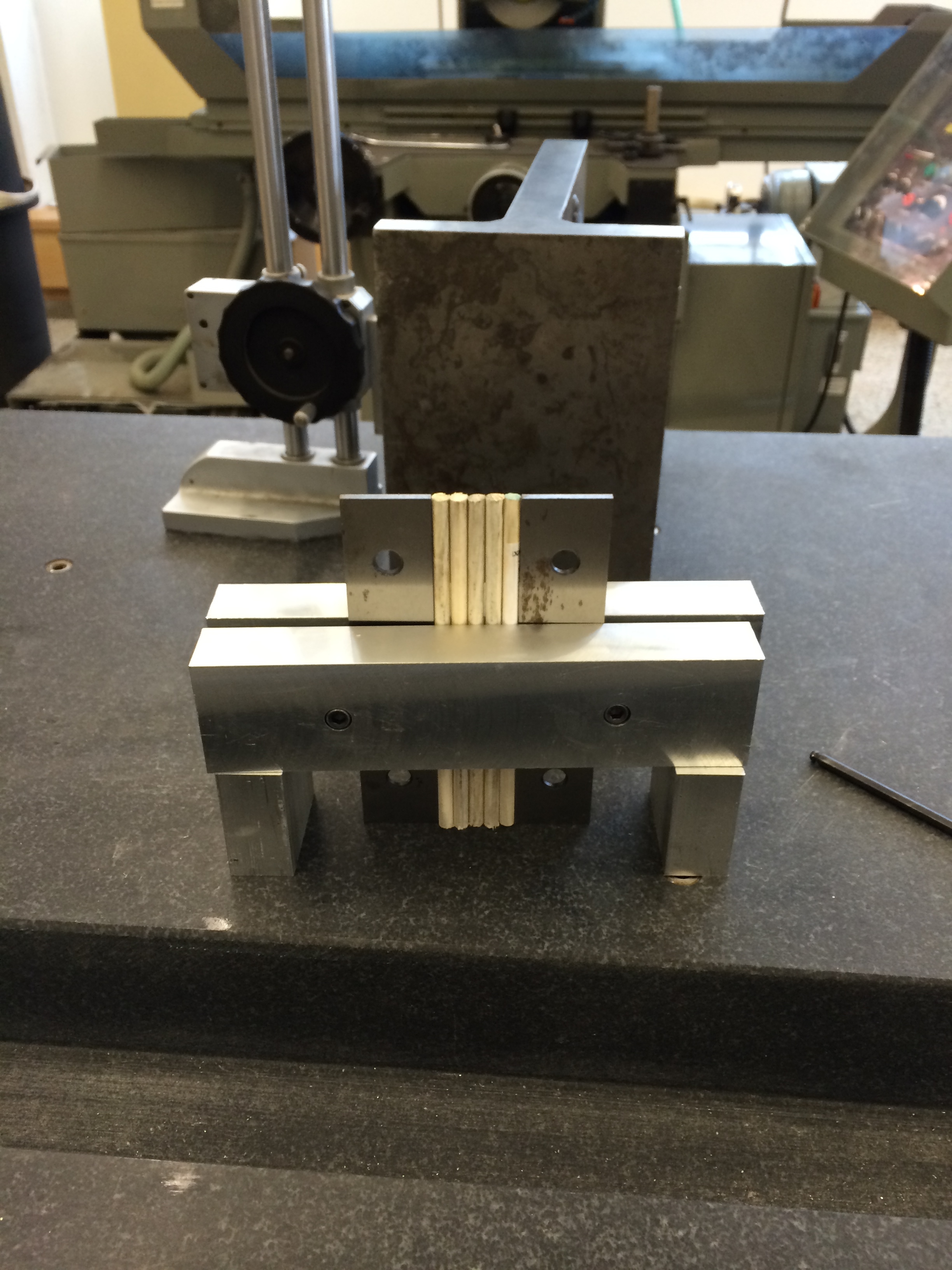
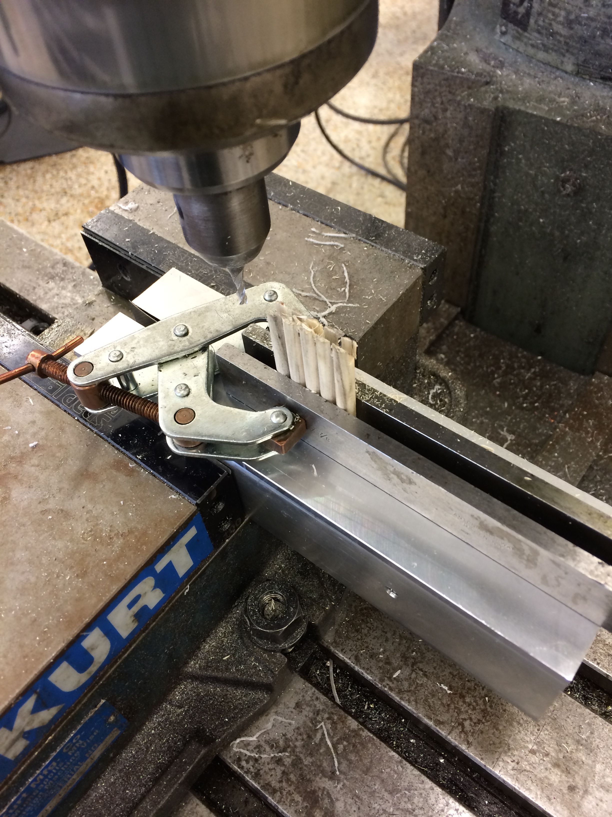
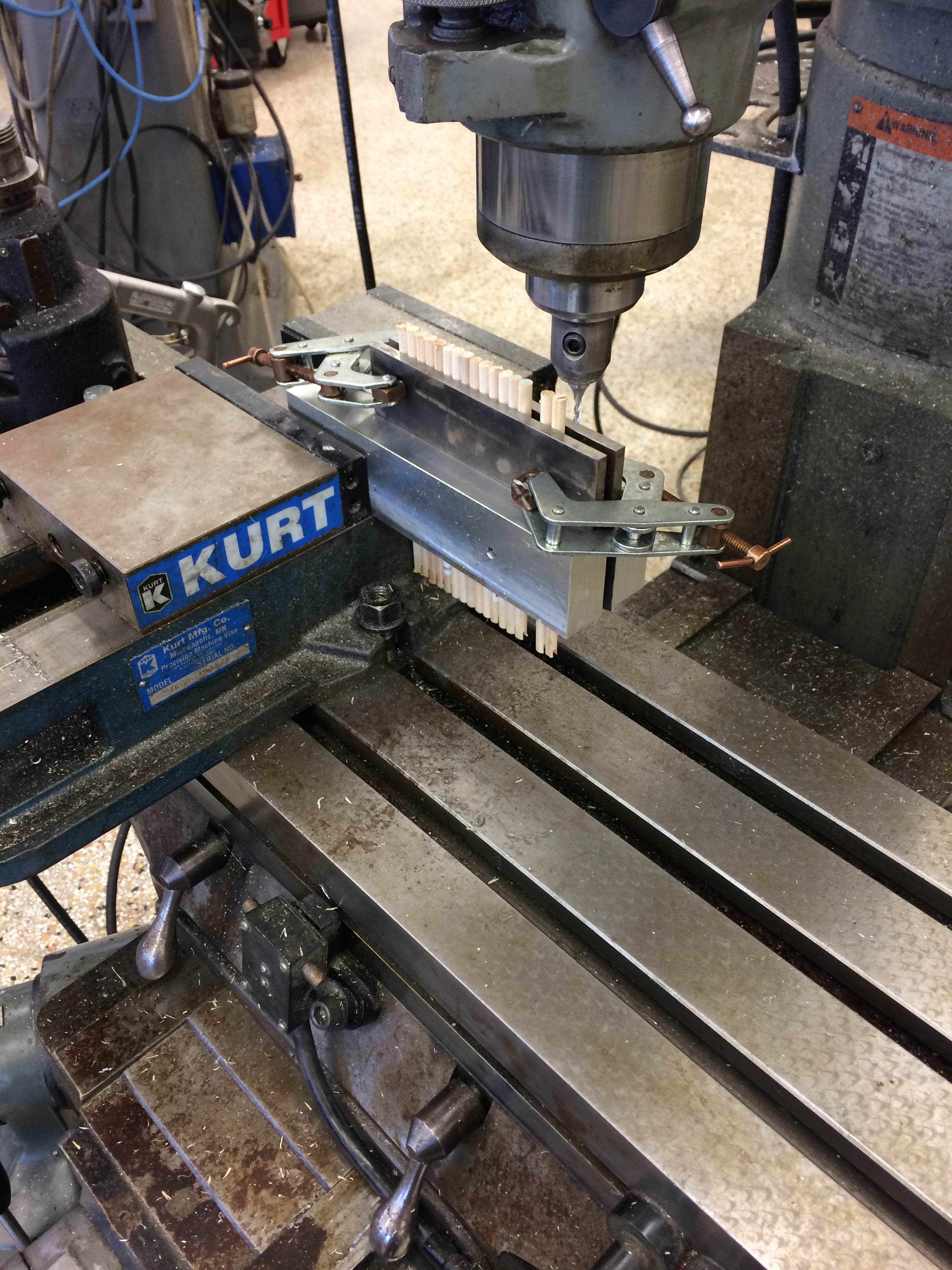
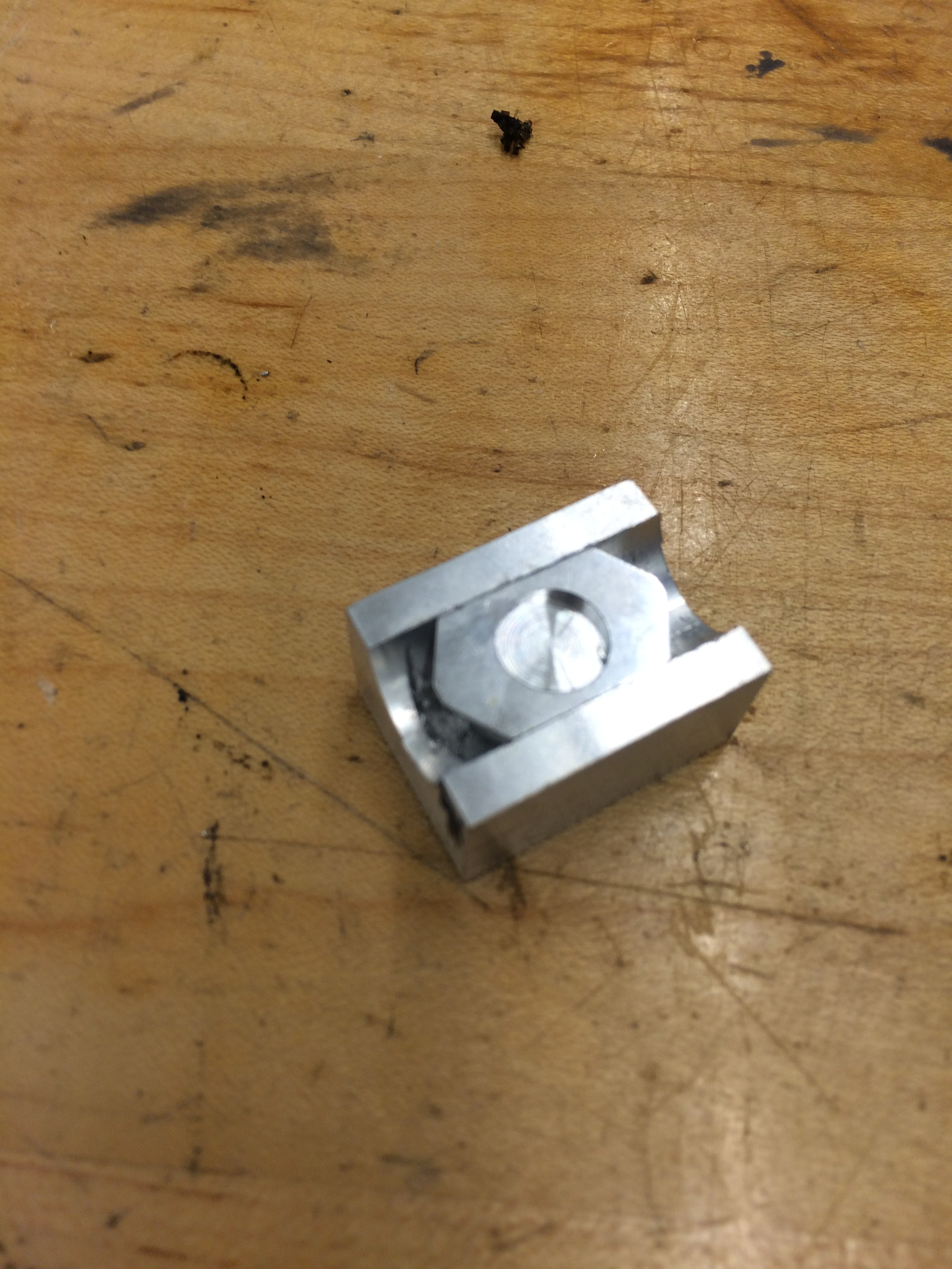
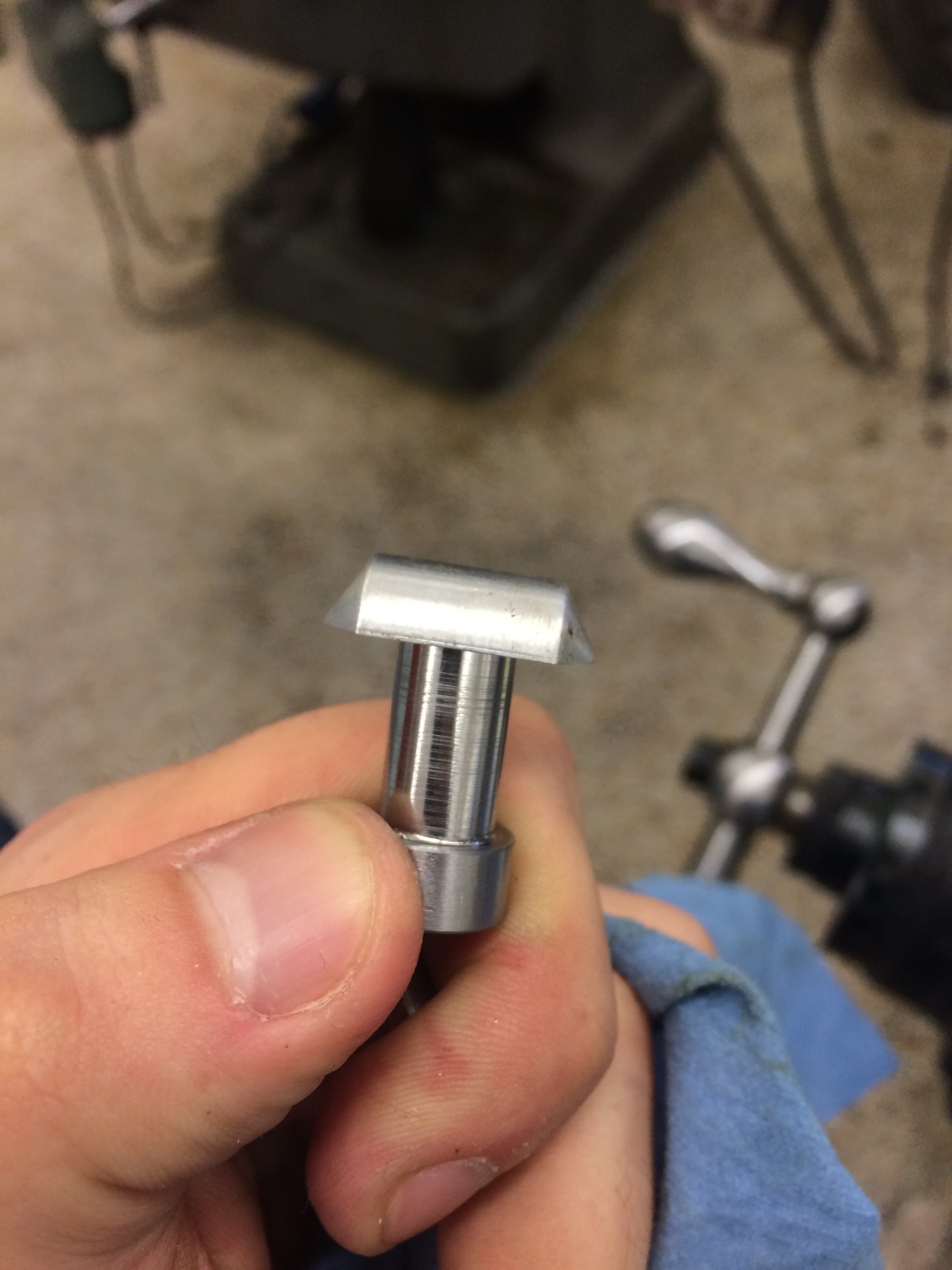
This weekend was our graduation, and with everyone's family in town I took my girlfriend's sister to the machine shop to teach her some machining. She helped make part of the locket I'm making for my girlfriend. We had to cut shallow flat bottomed holes in the barrels for the pictures to go in. Because the barrels have a semicircular geometry, they could not be mounted on the table using a regular vise or any of that hardware. So we made a custom fixture to hold the barrel for the hole cutting operation.

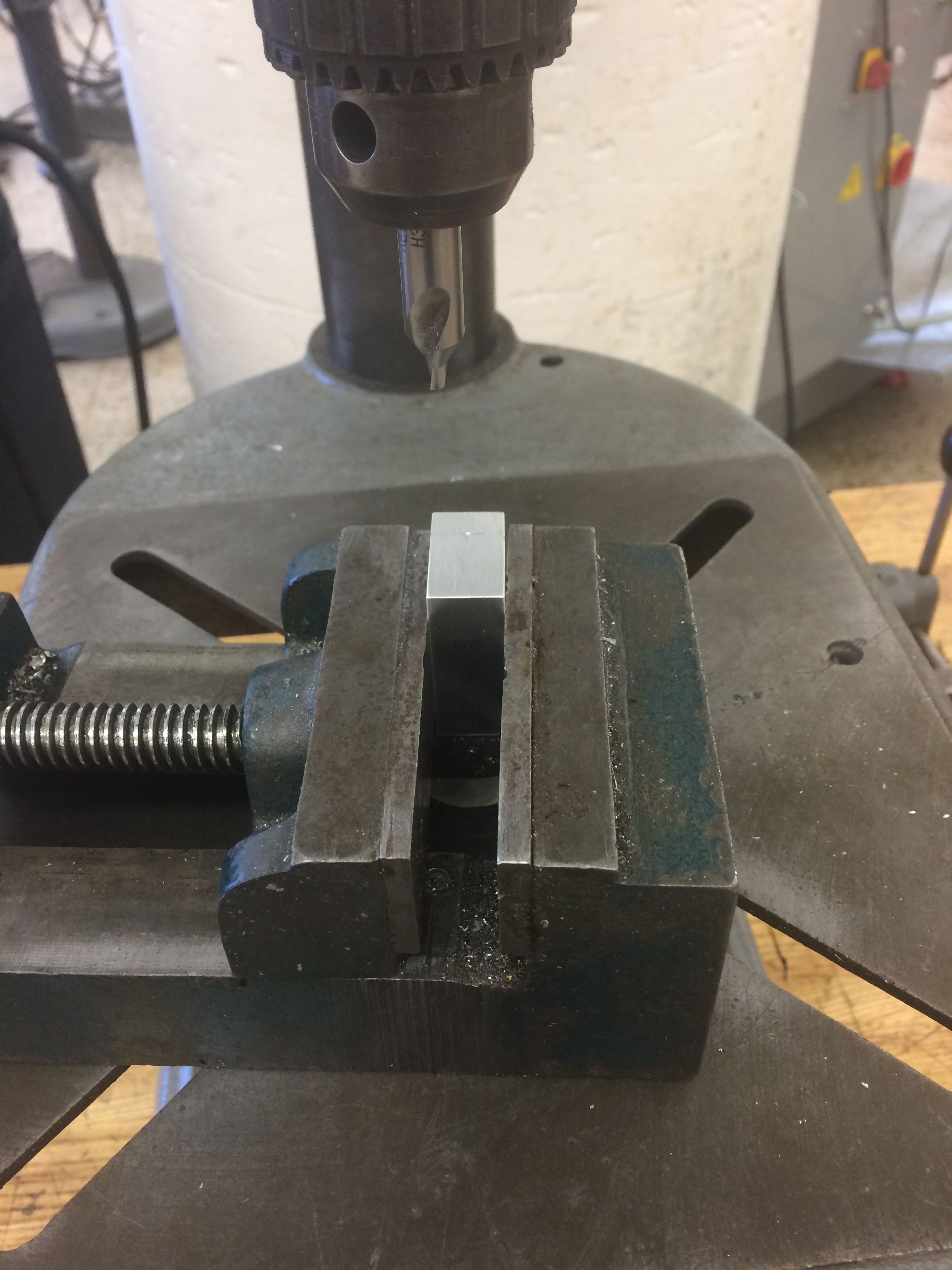
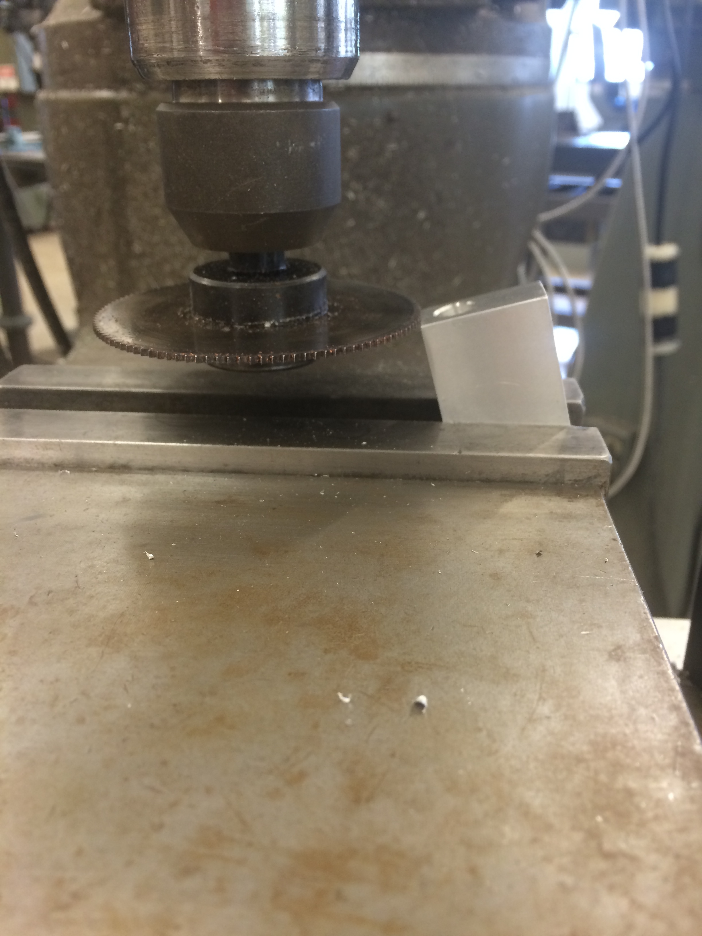
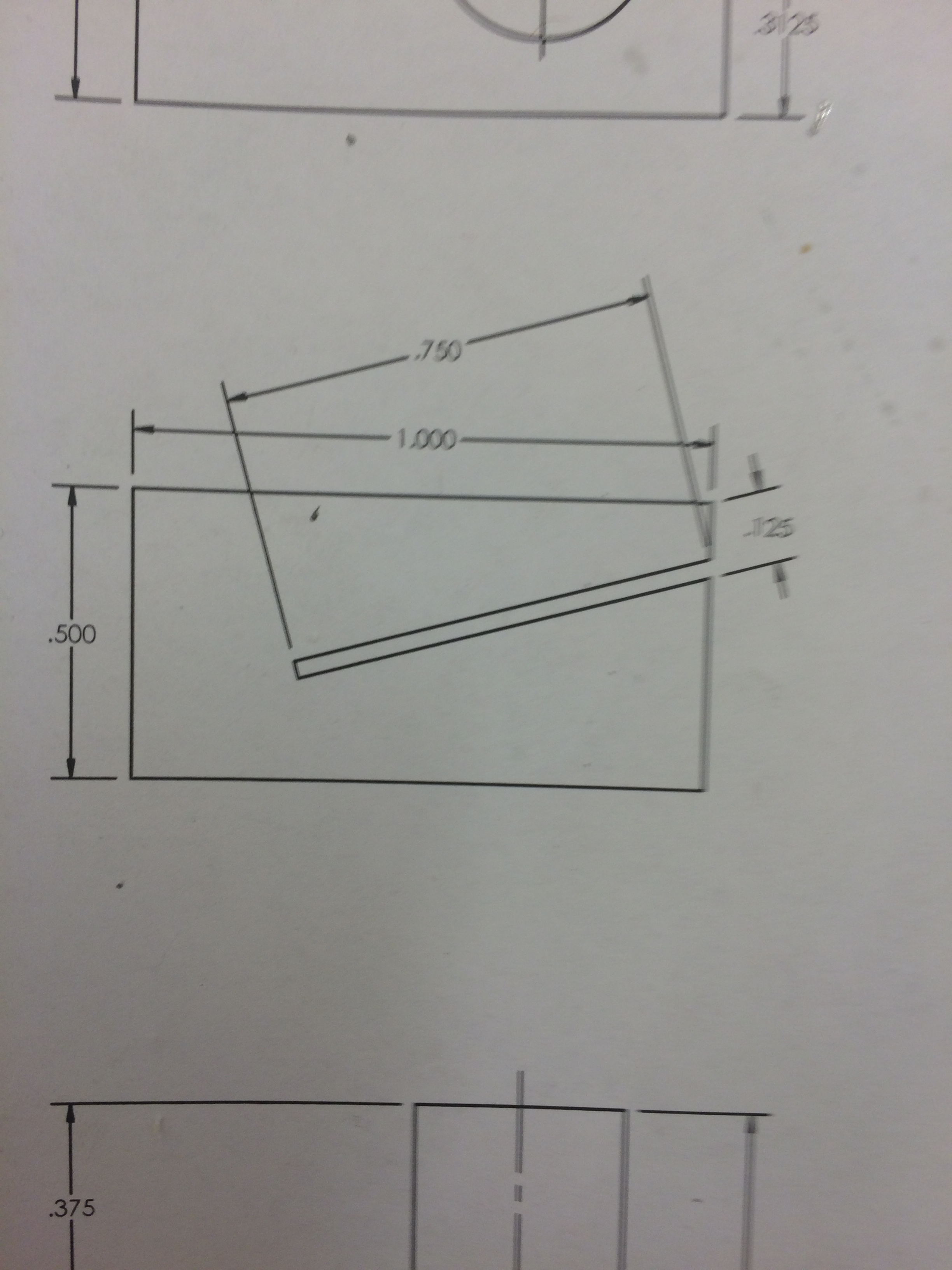
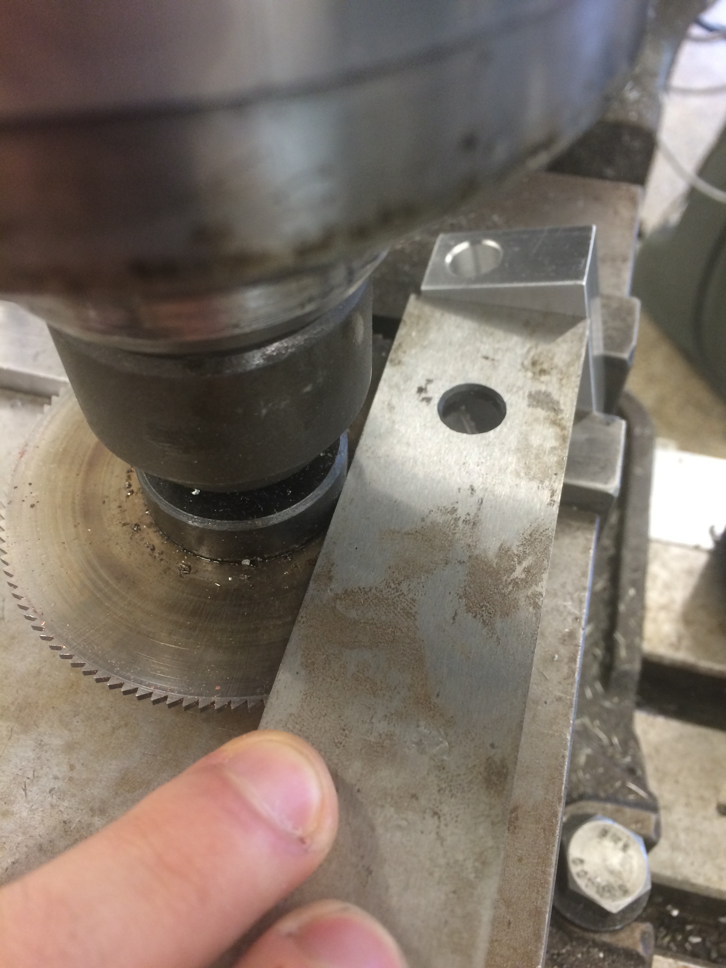
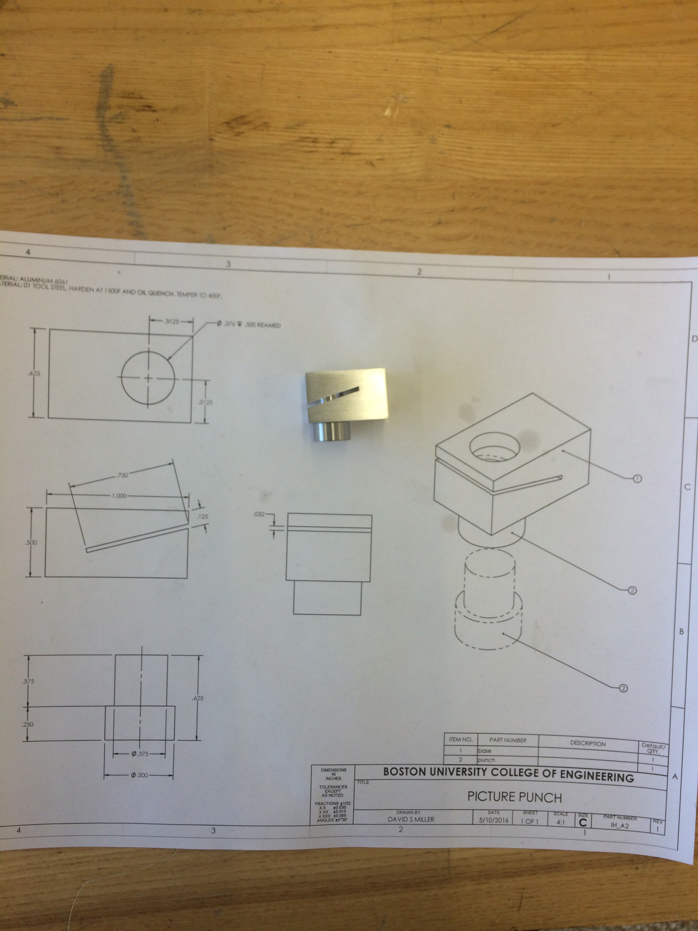
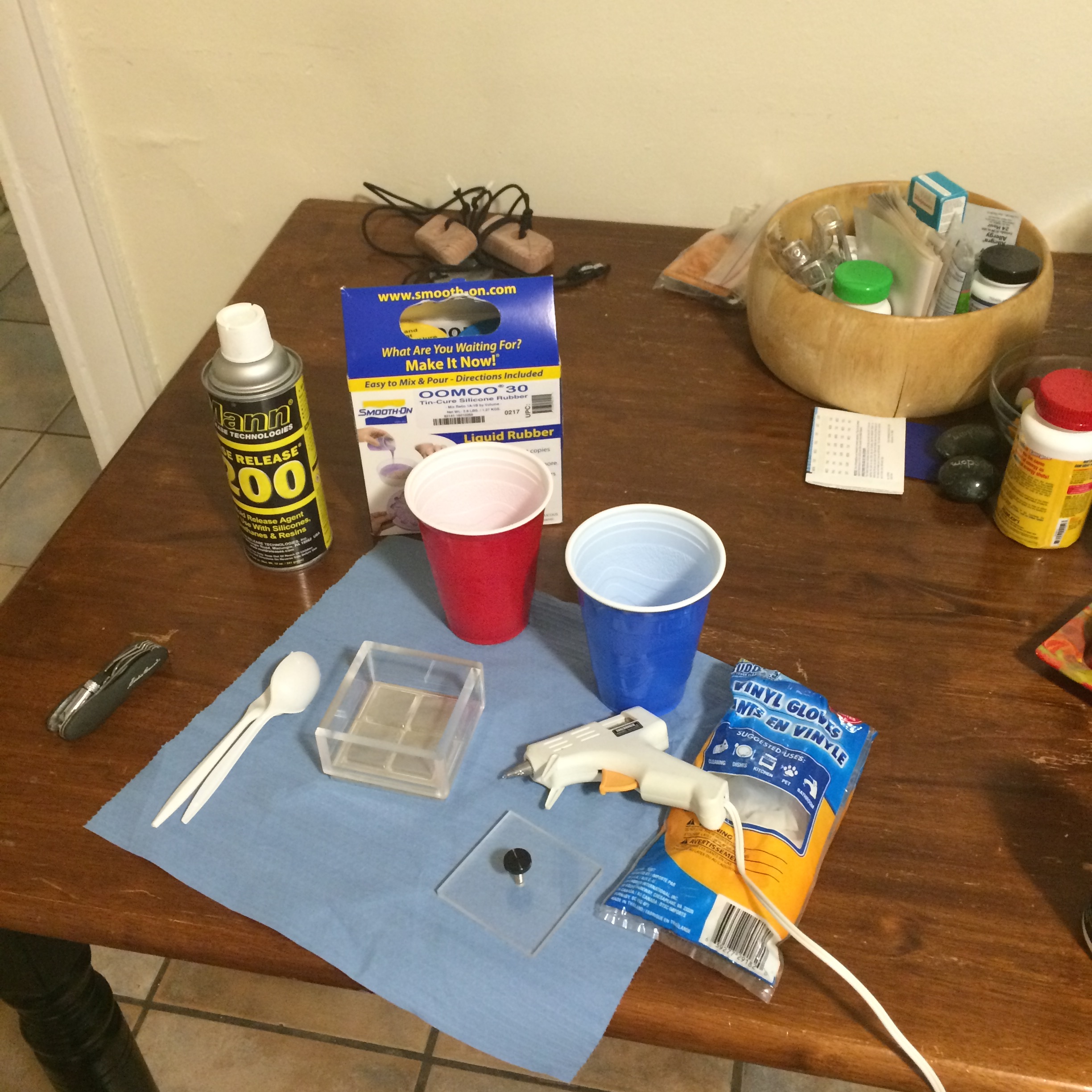
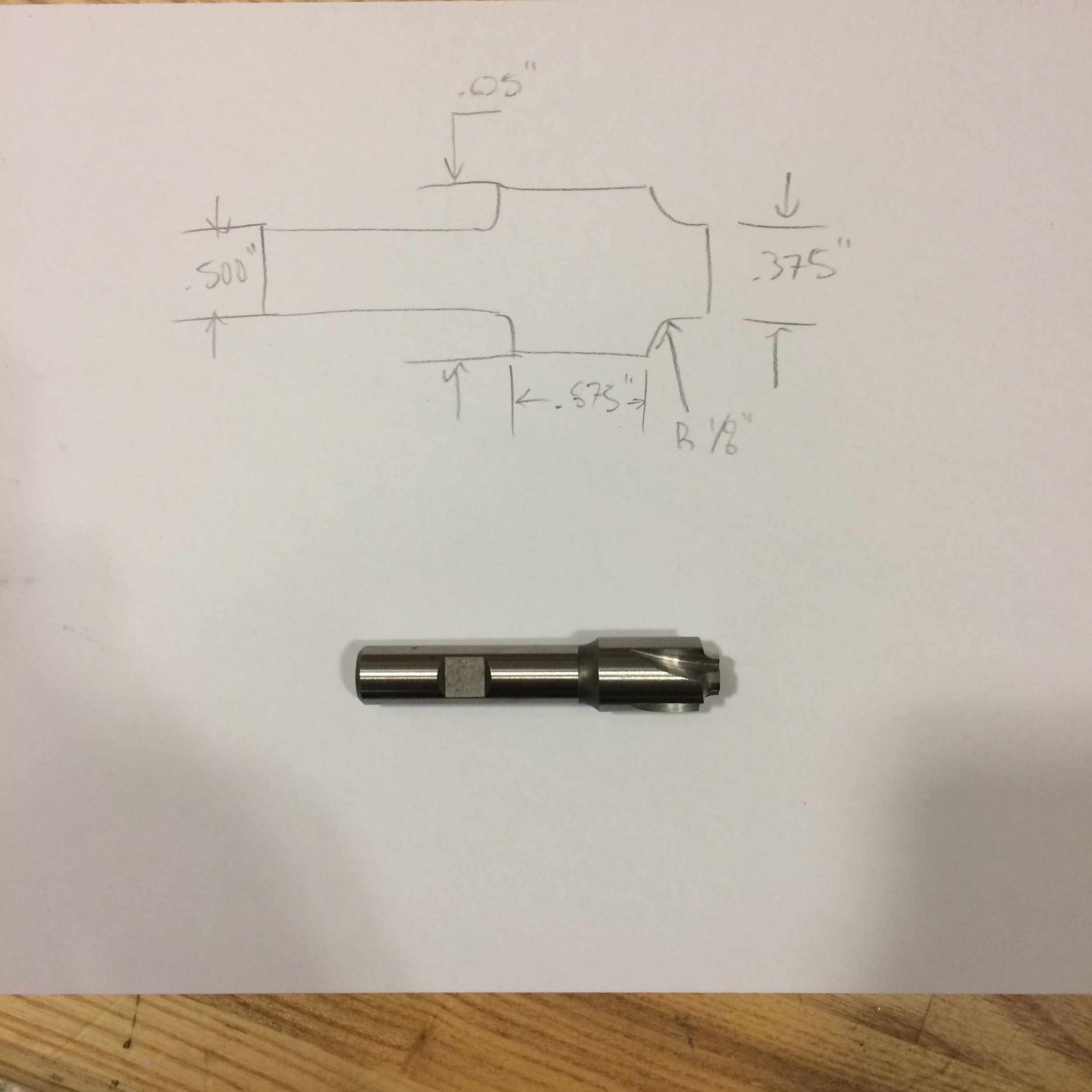
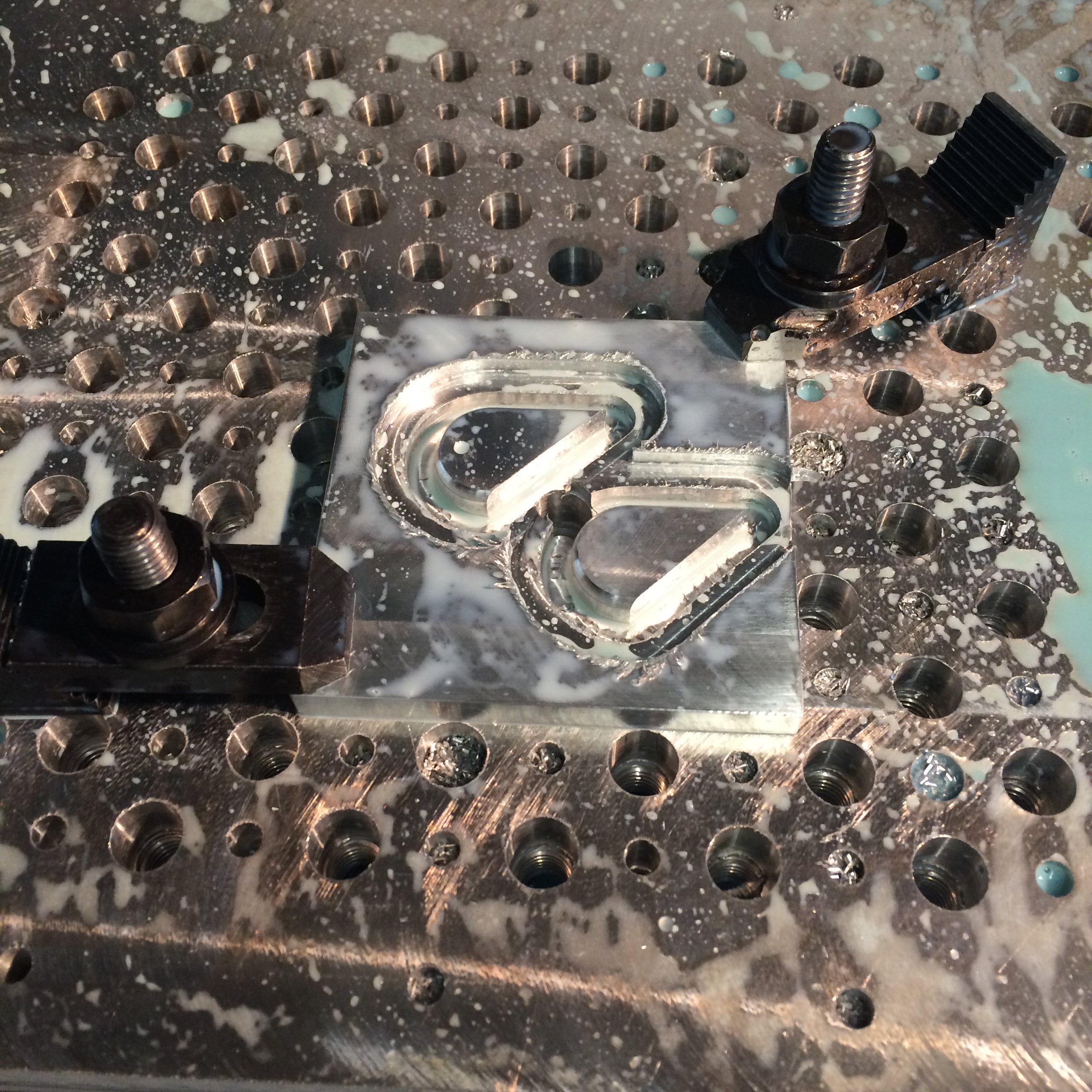
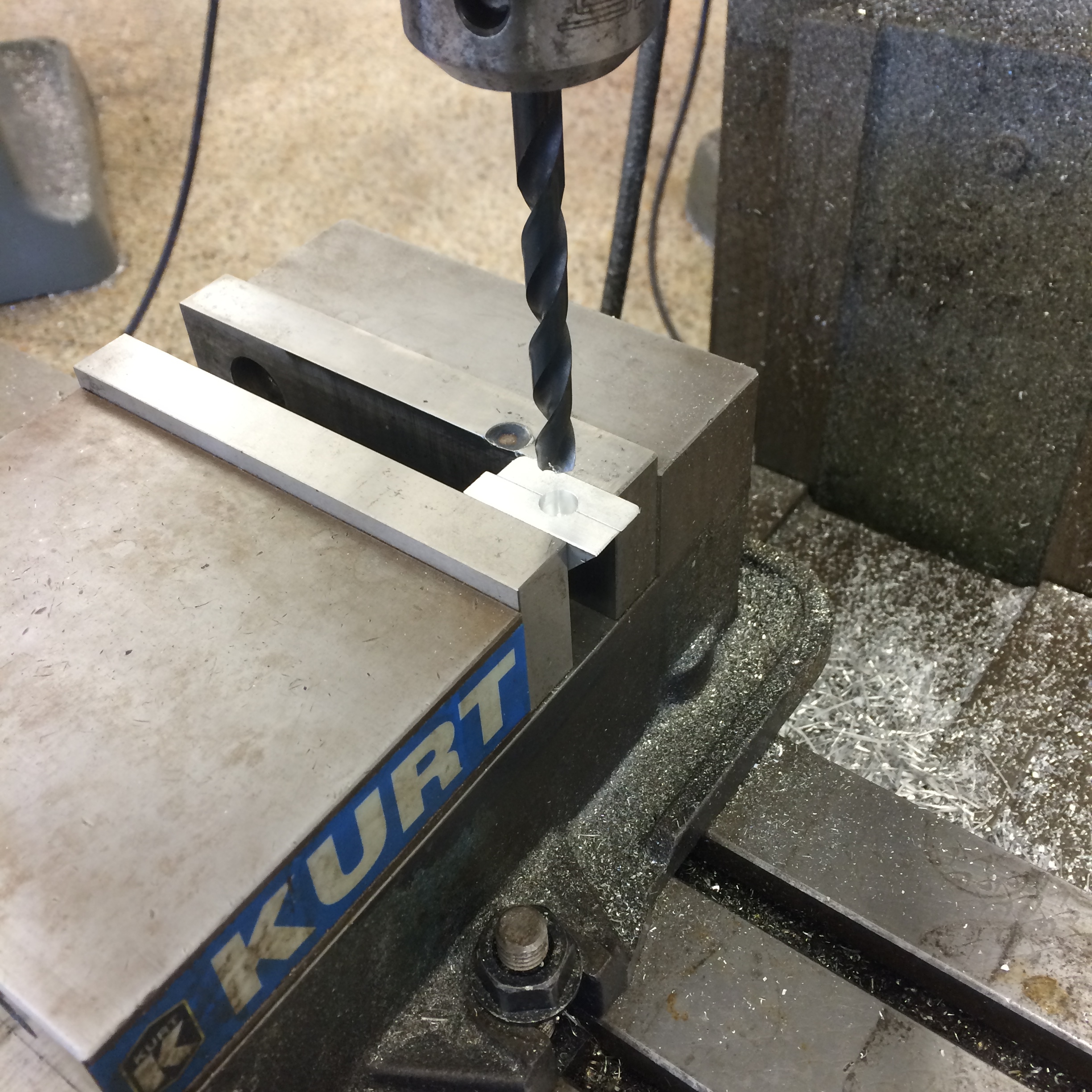
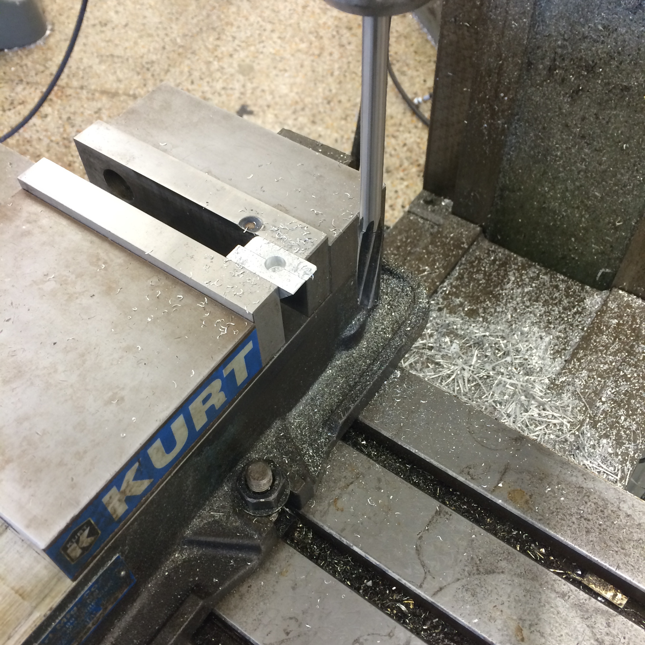
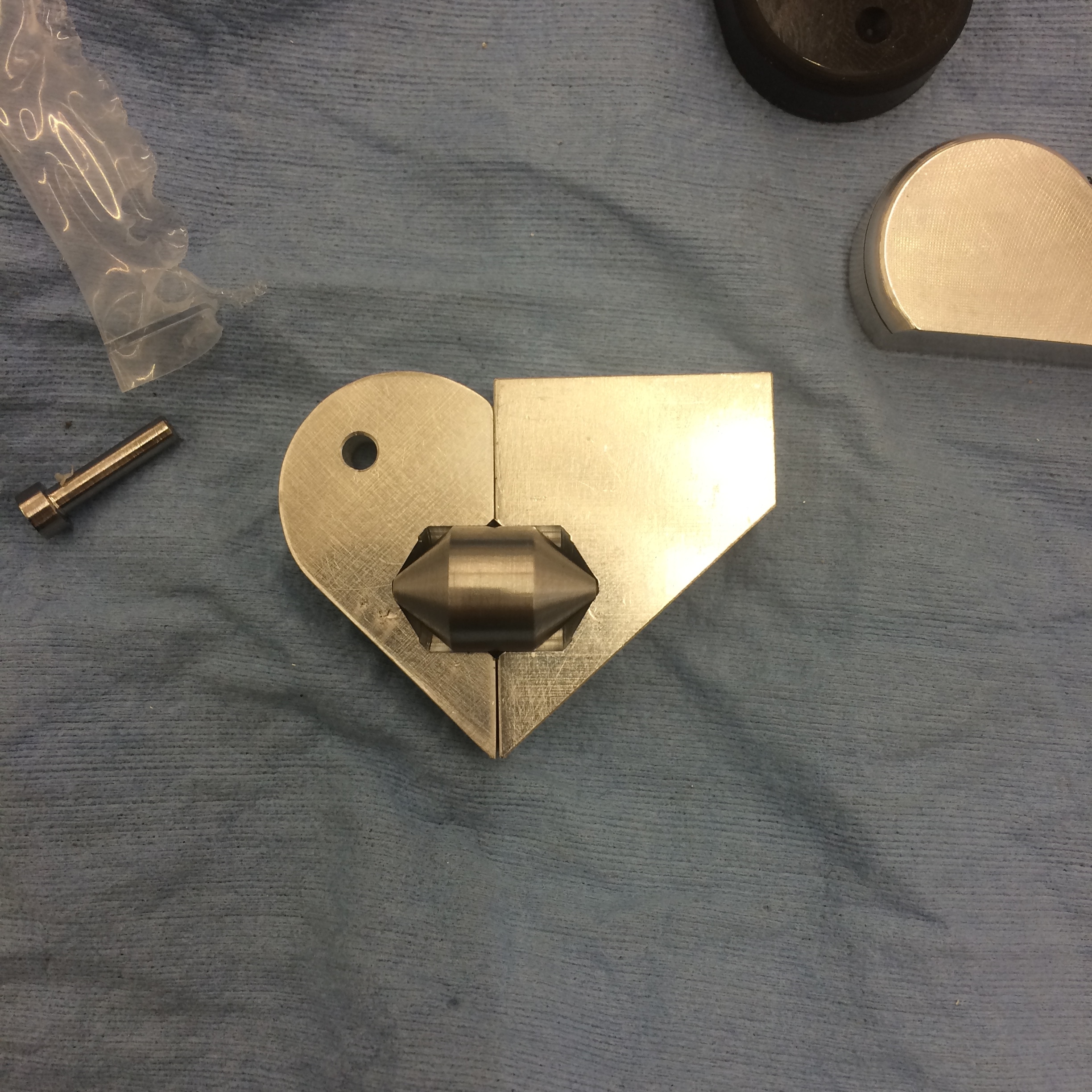
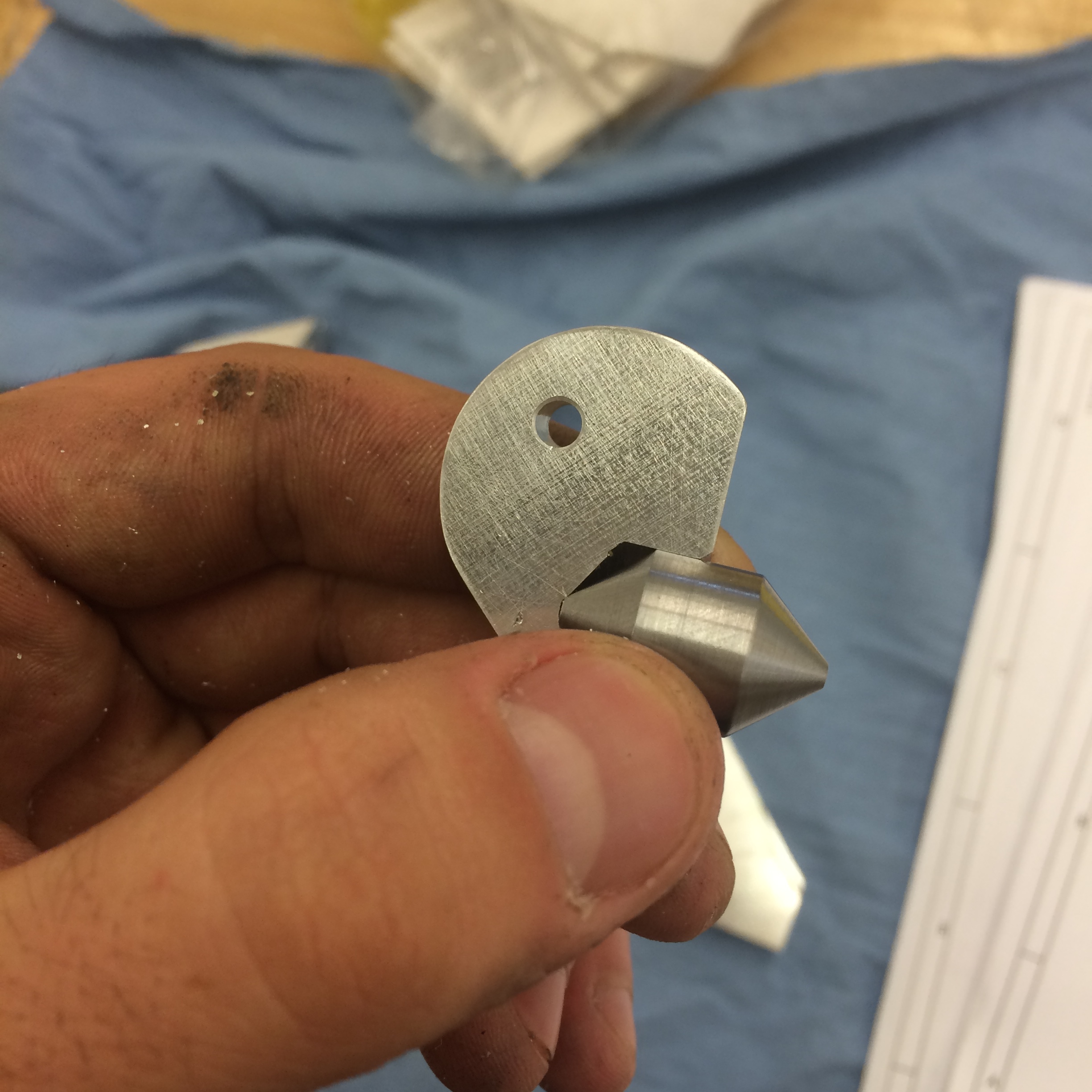
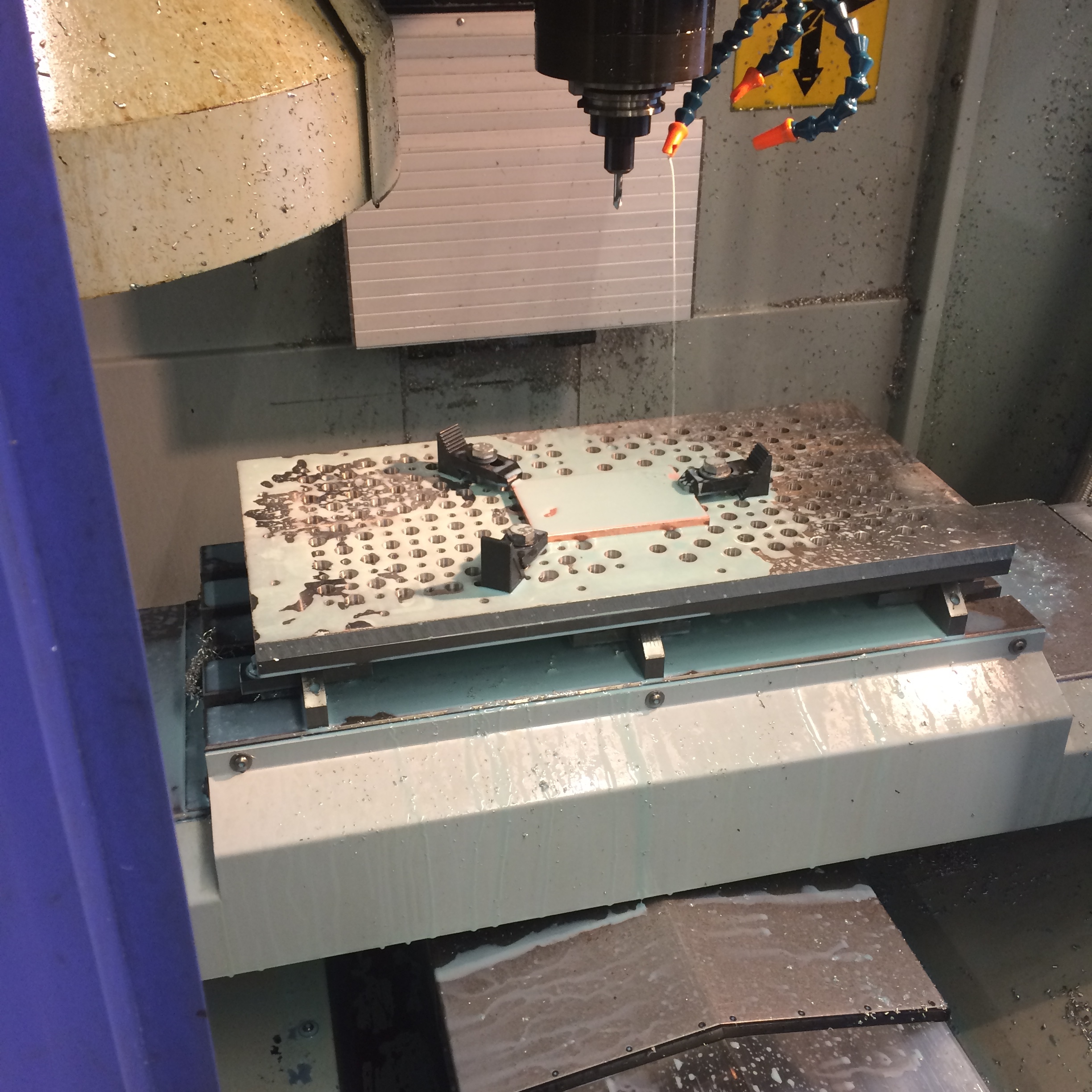
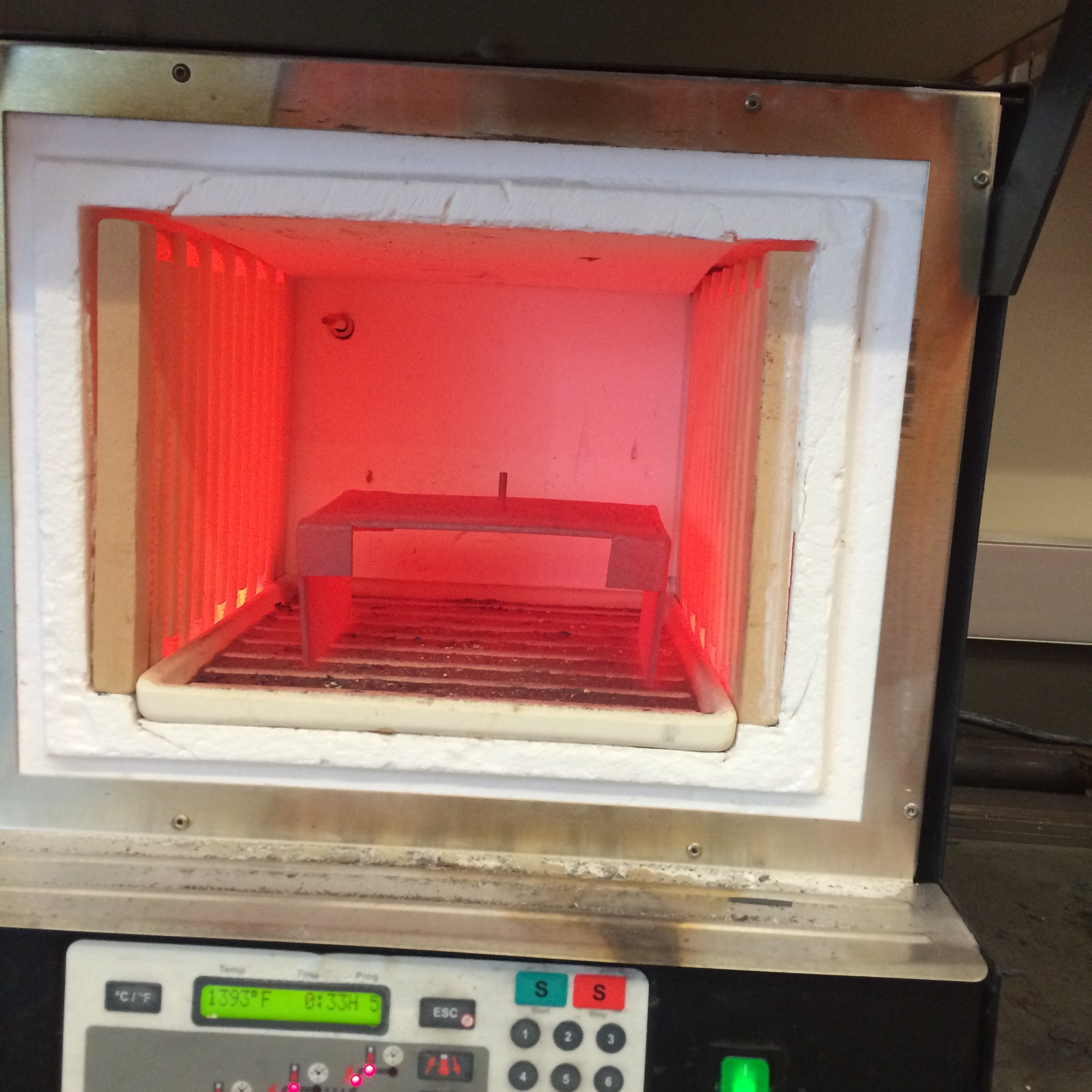
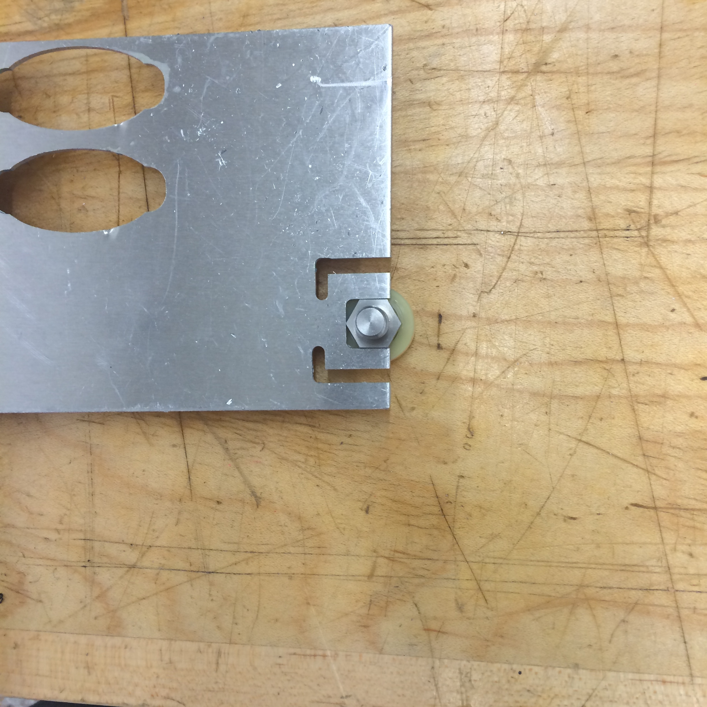
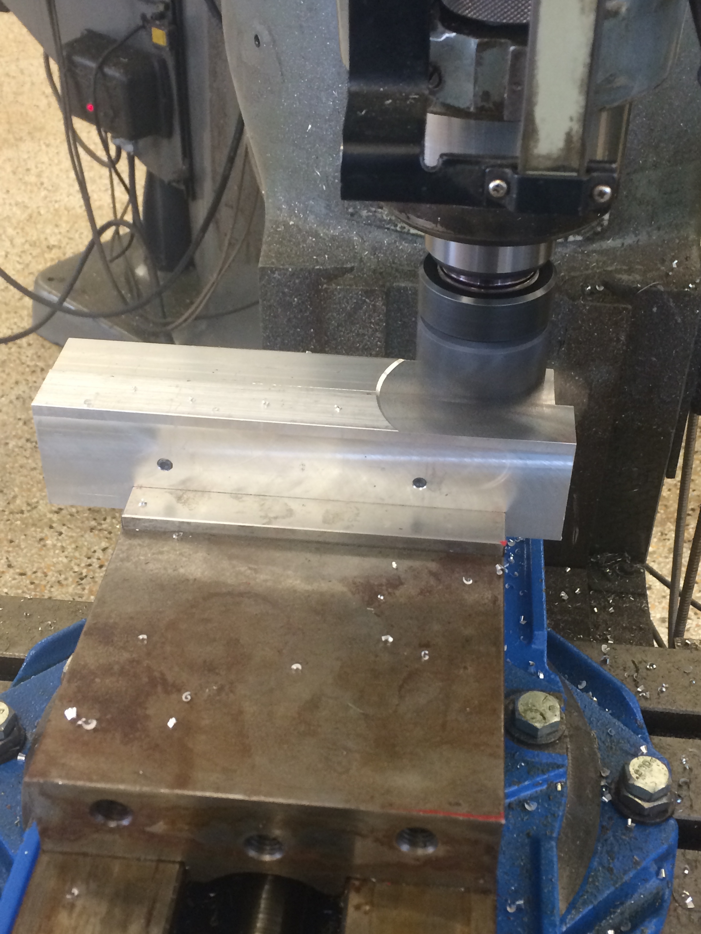
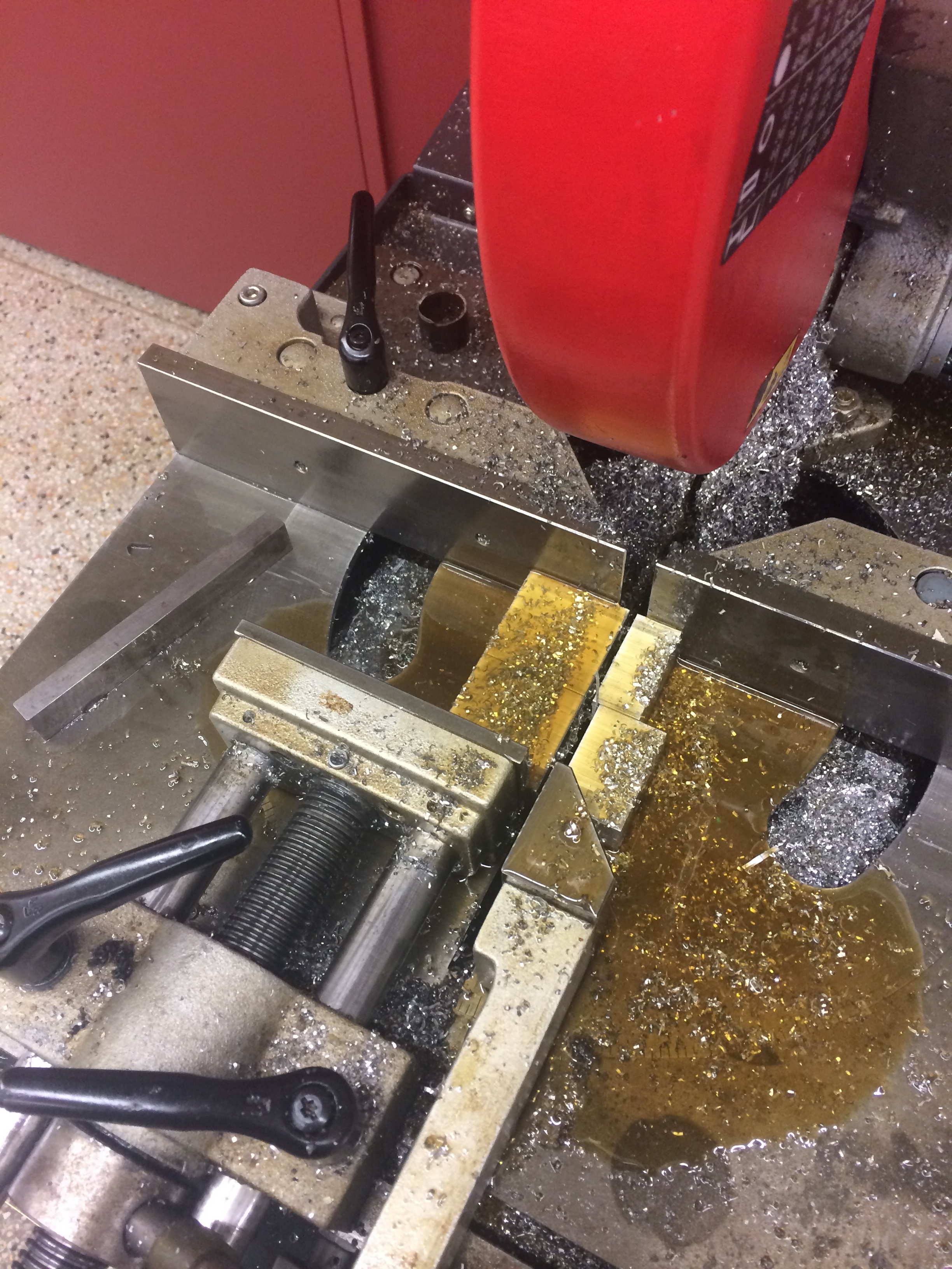
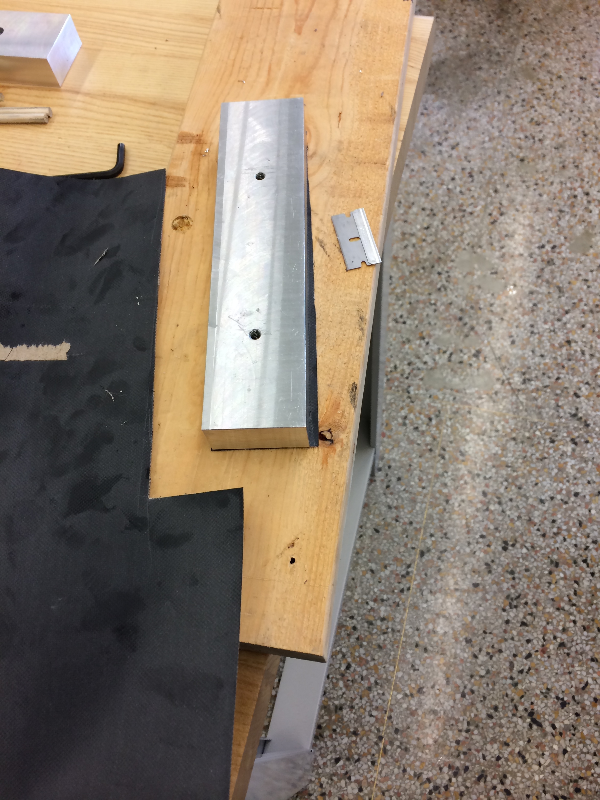
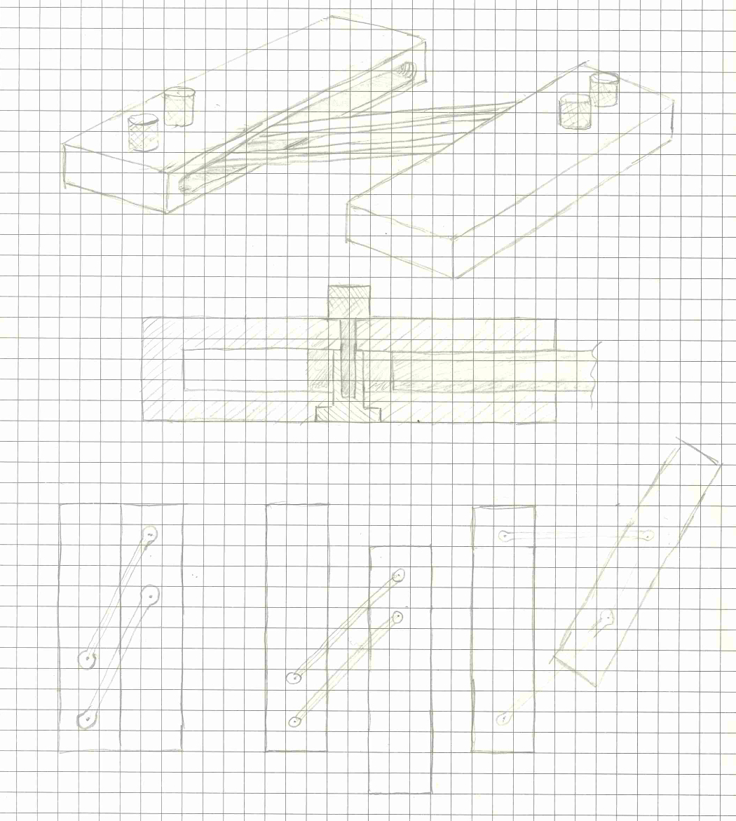
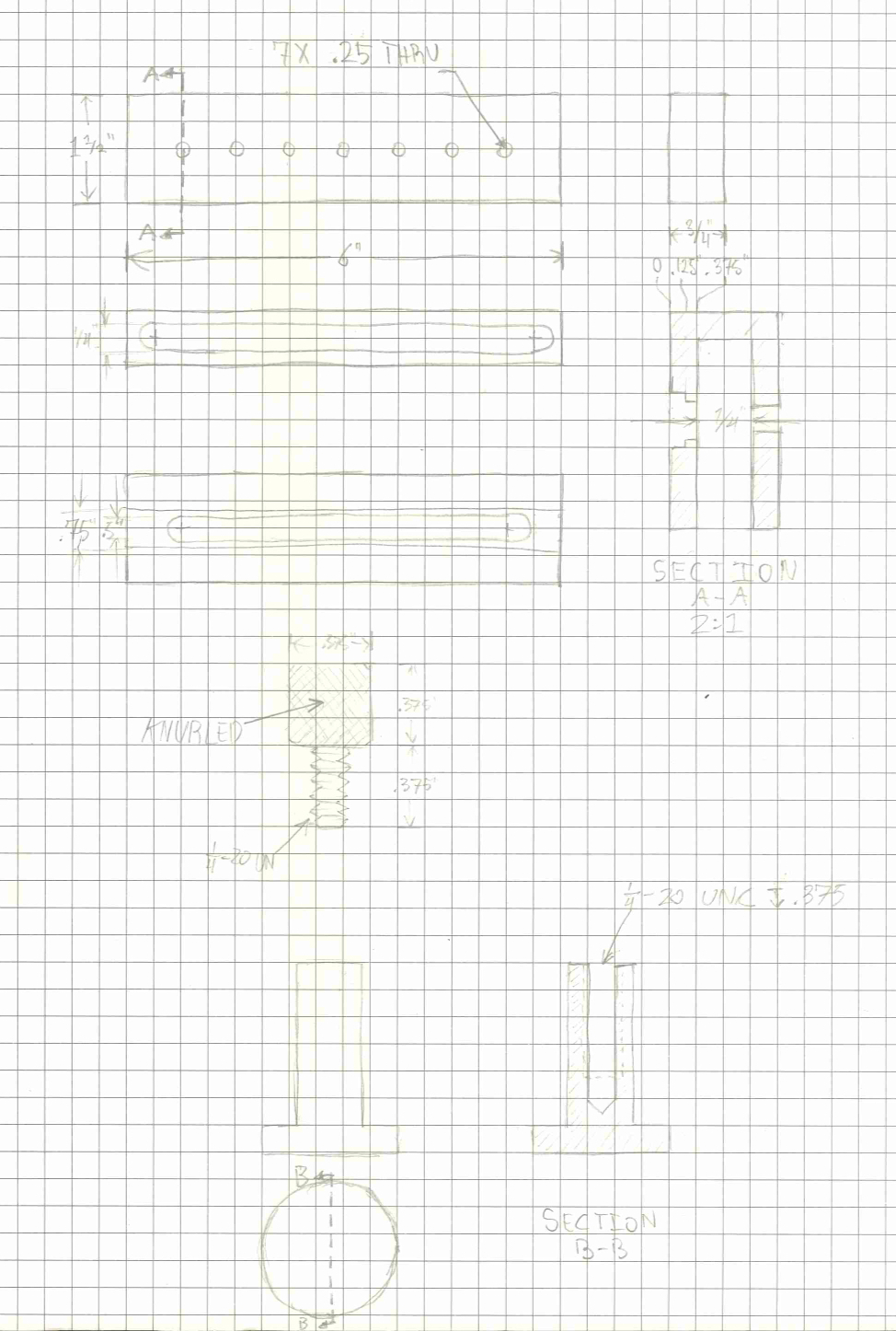
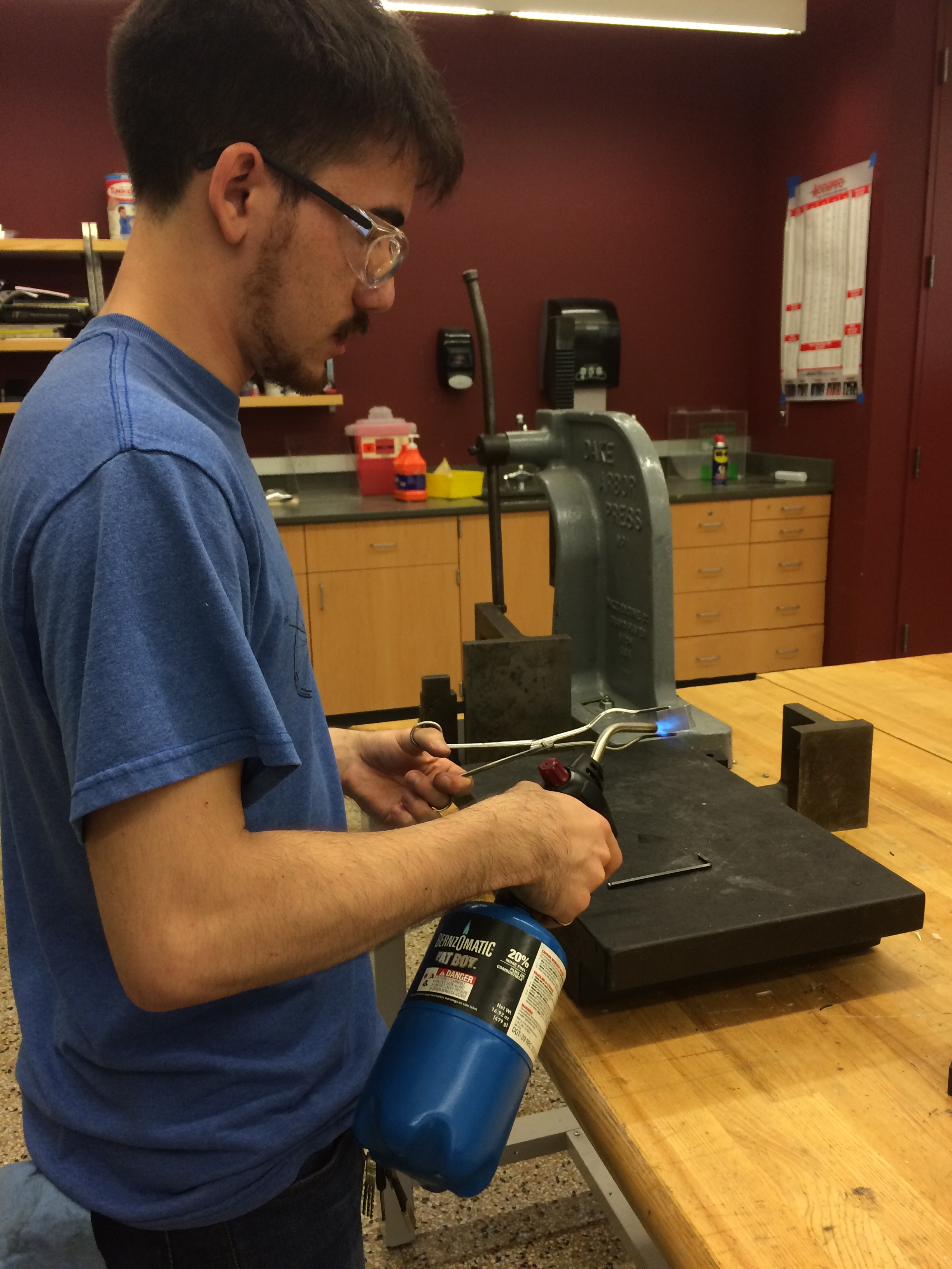
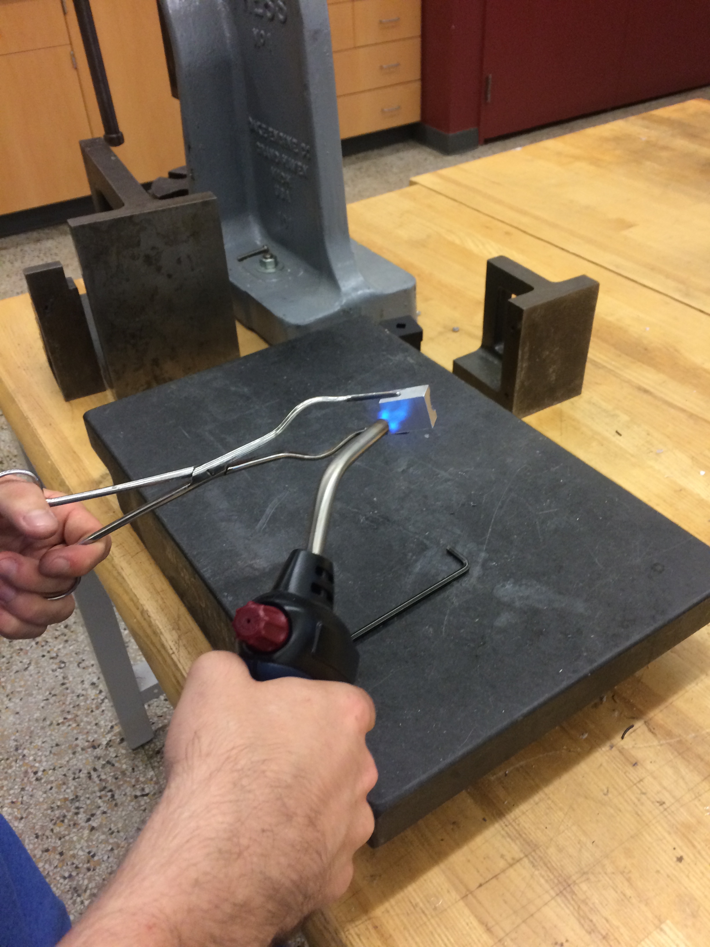
We used a 1/2" ballmill to cut a groove in a square piece of aluminum so that the 1/2" barrel would fit snug in the groove. We then superglued the barrel in the groove and clamped the whole thing in the vise to drill the hole .050" deep with a 3/8" flat end mill. We then heated it up with a propane torch to release the superglue bond and used some acetone to get rid of any residue. Superglue is a very easy way to fix parts that would otherwise require the manufacture of a complex fixture or jig. I don't know if I would trust it for precision machine work though.

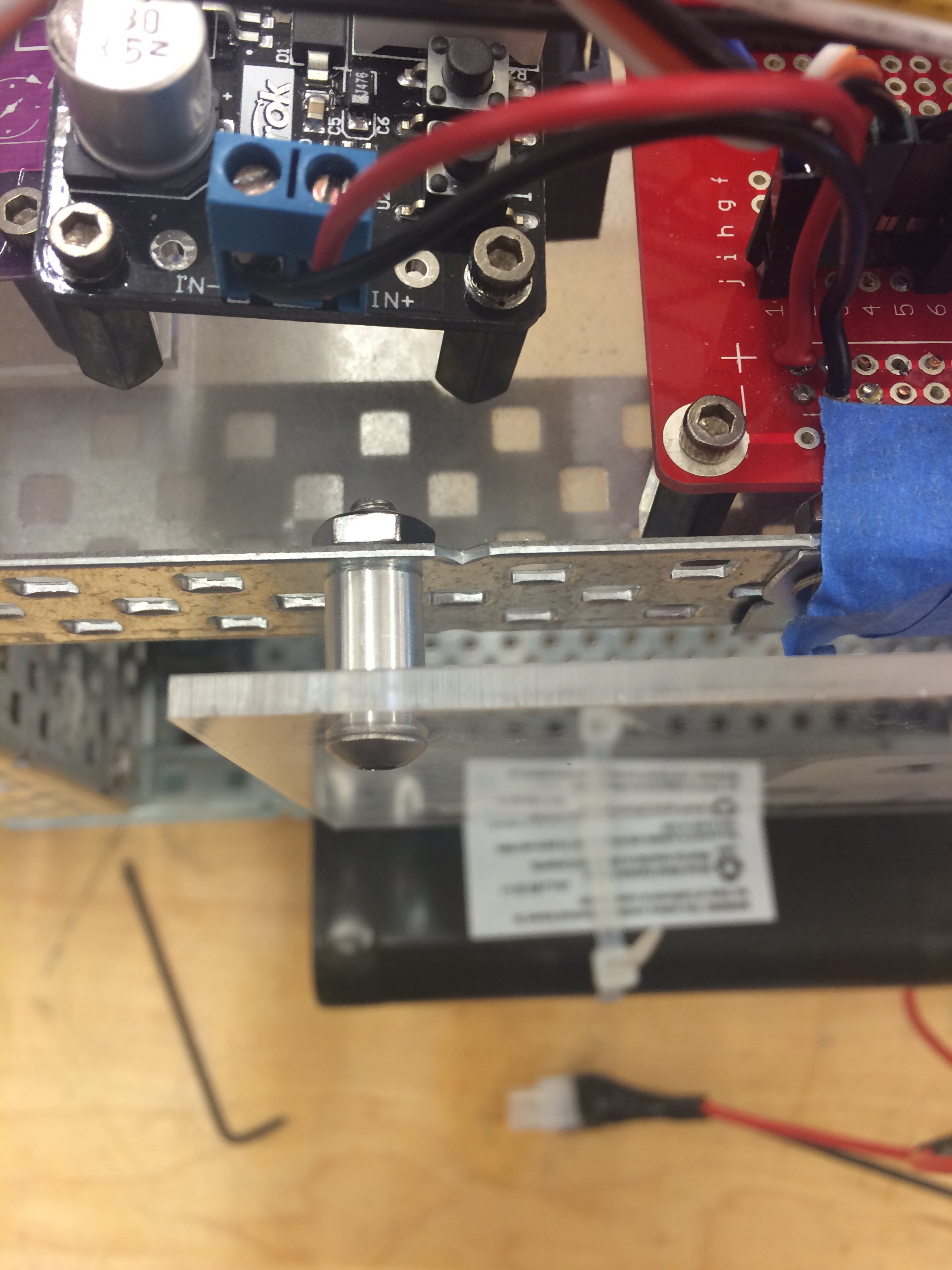
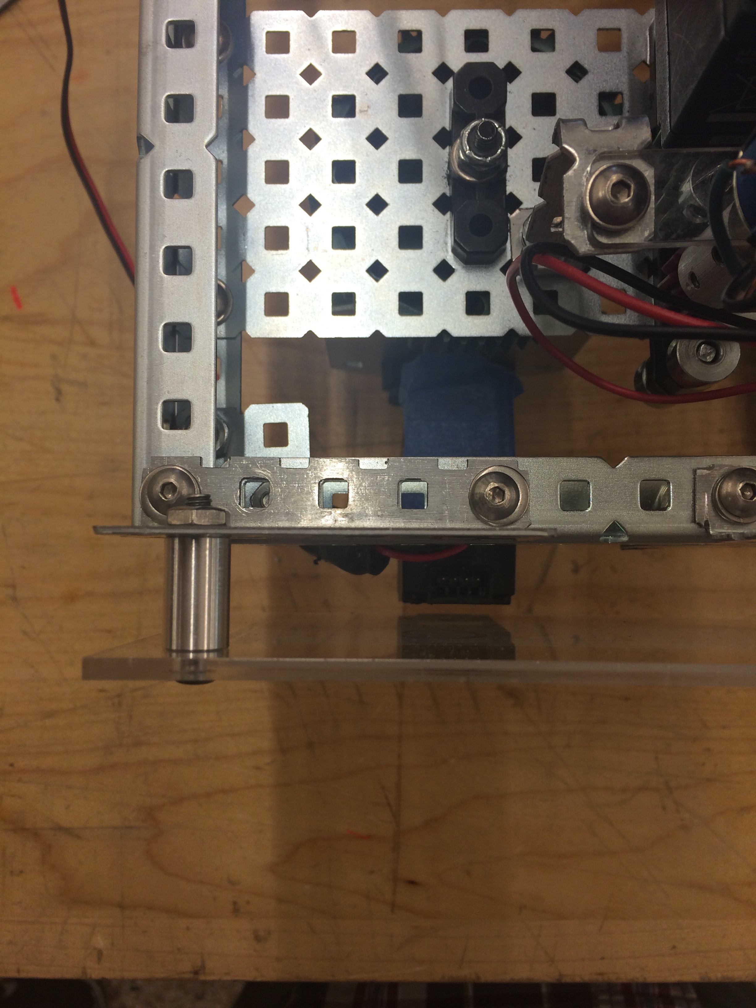
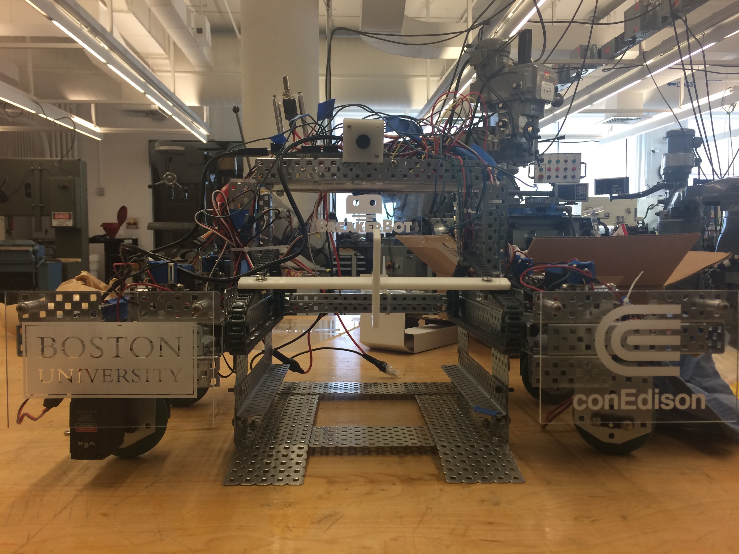
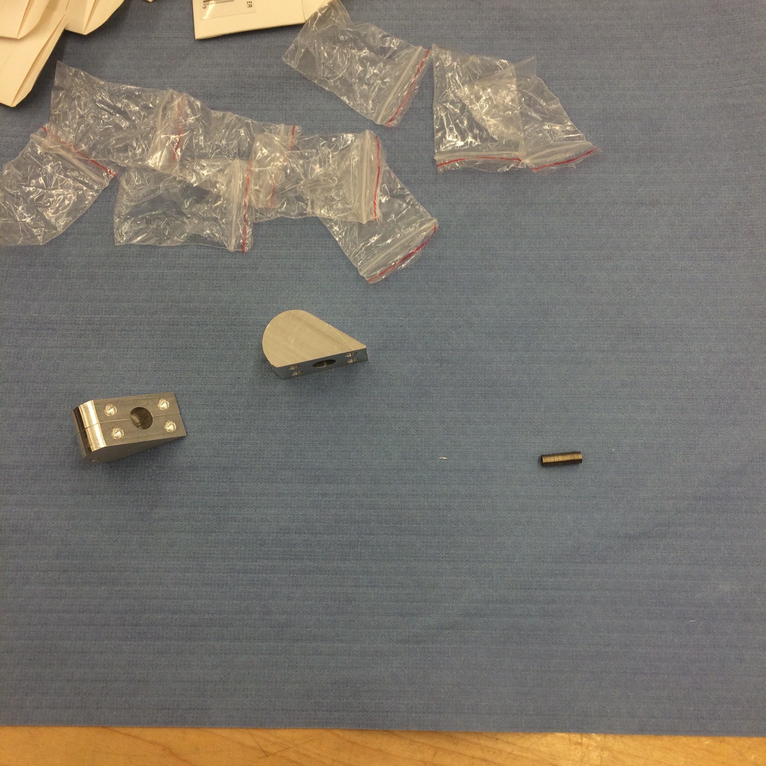
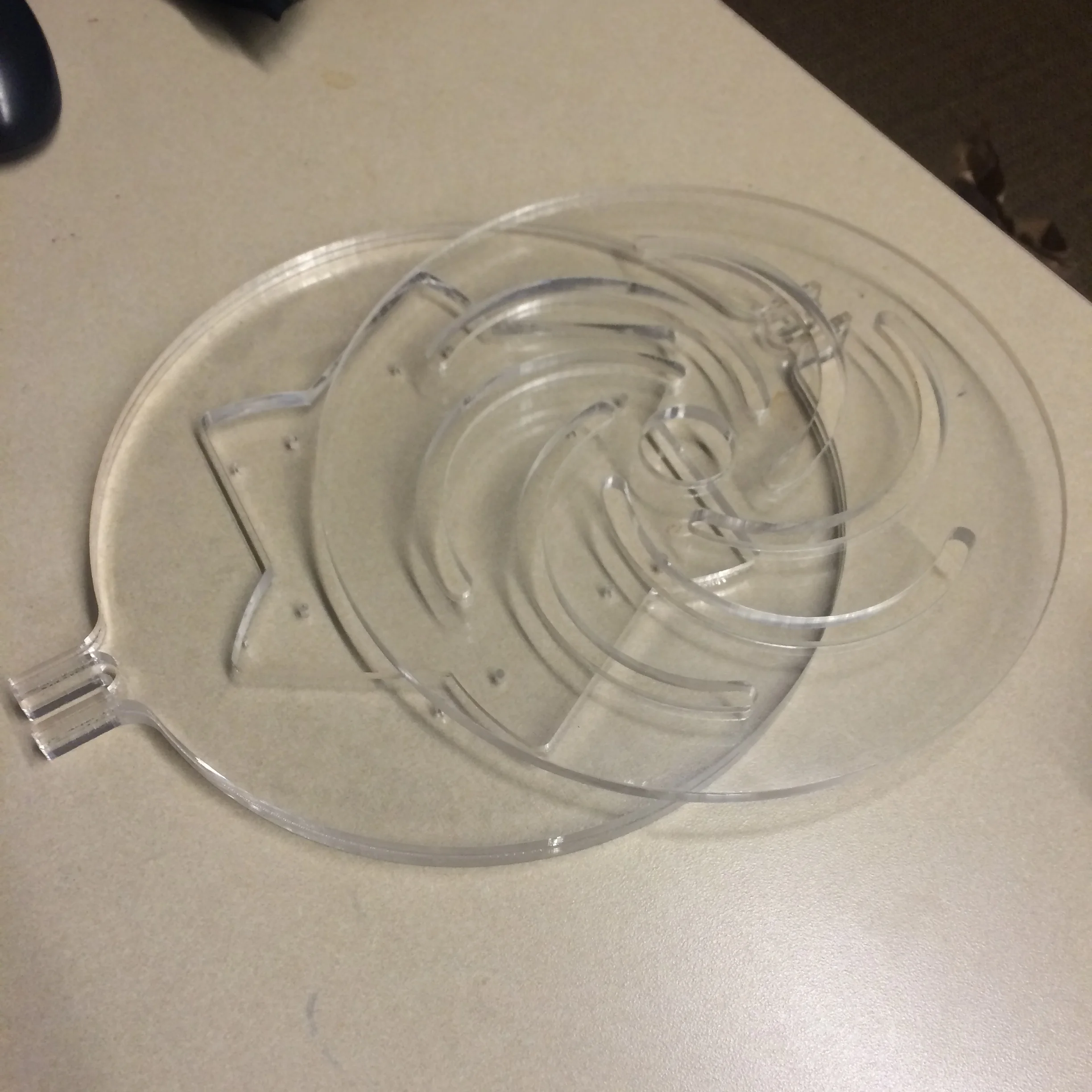
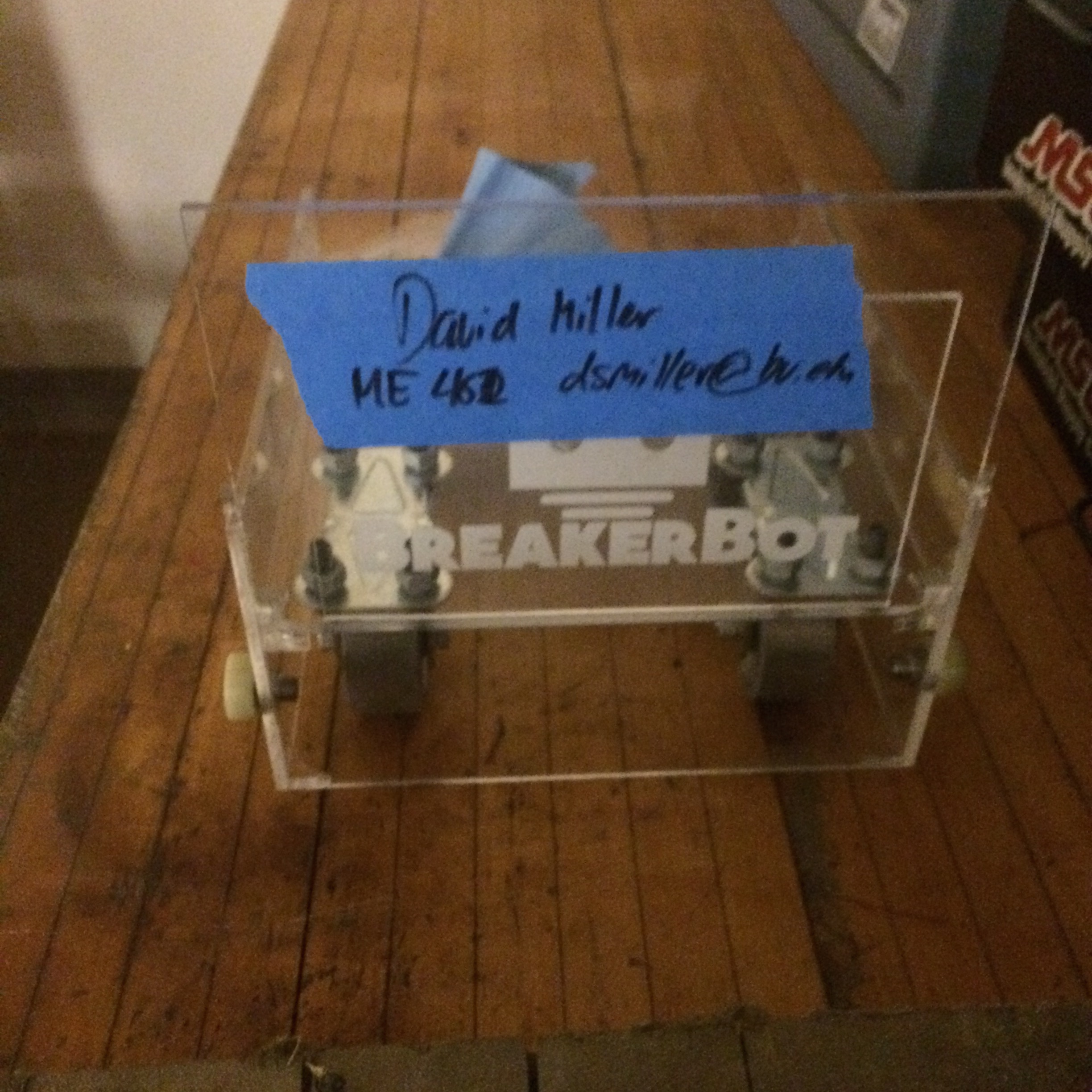
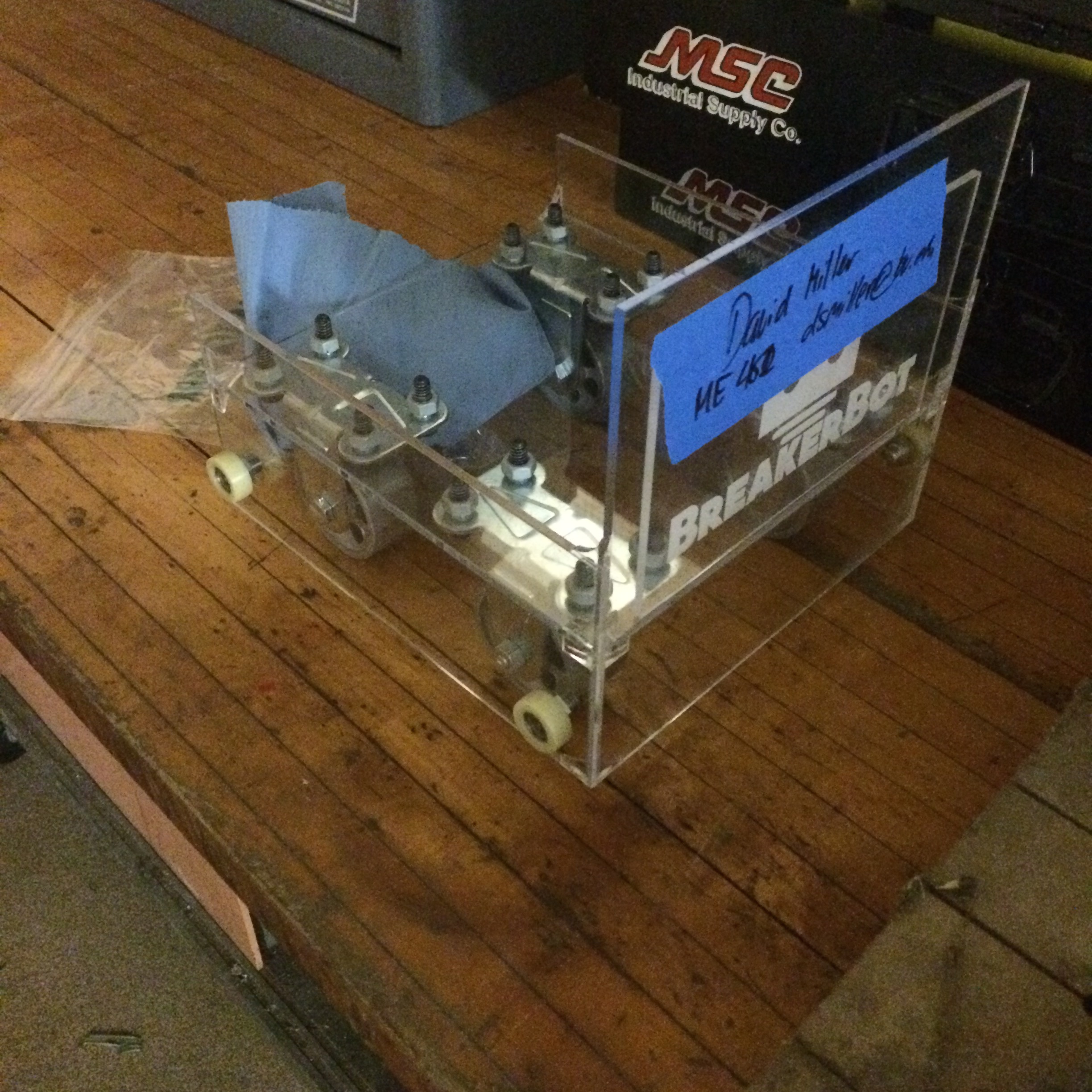
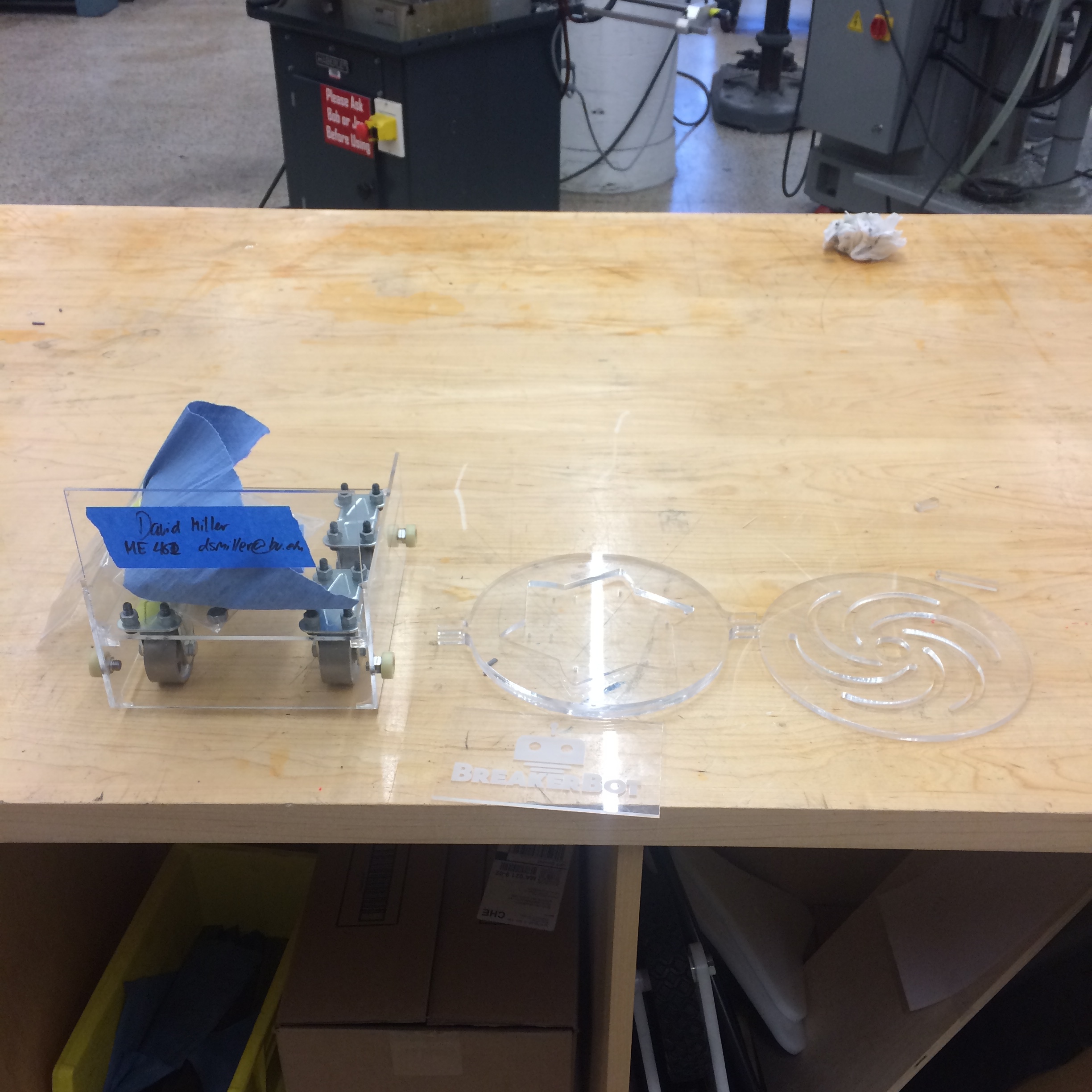
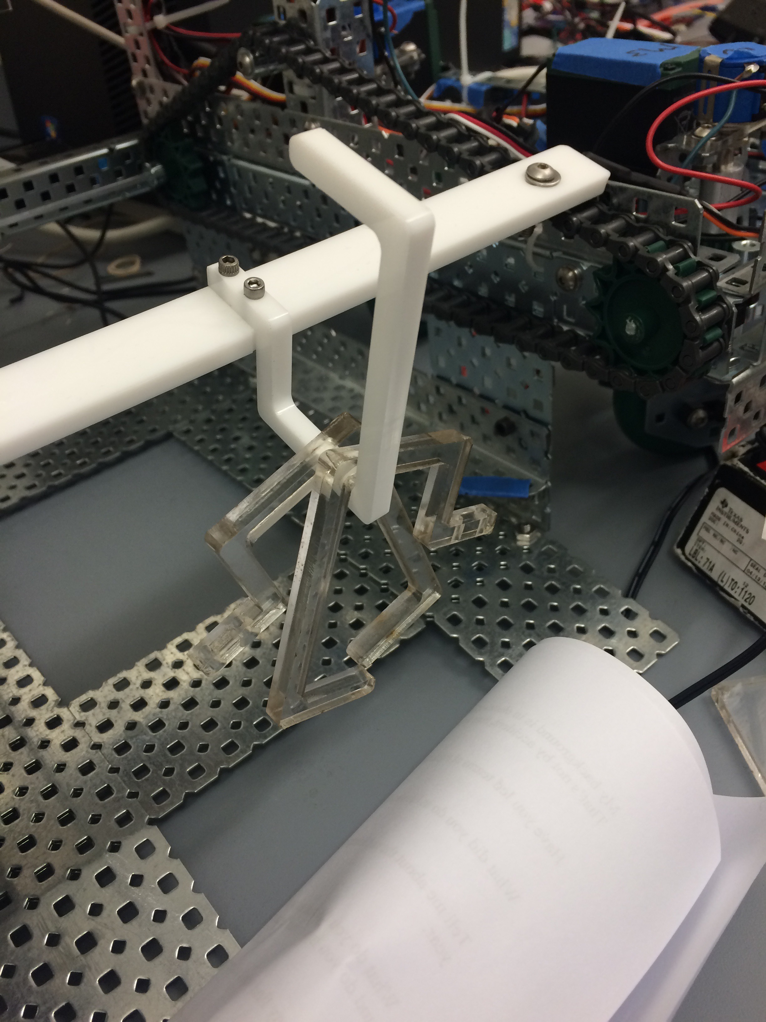
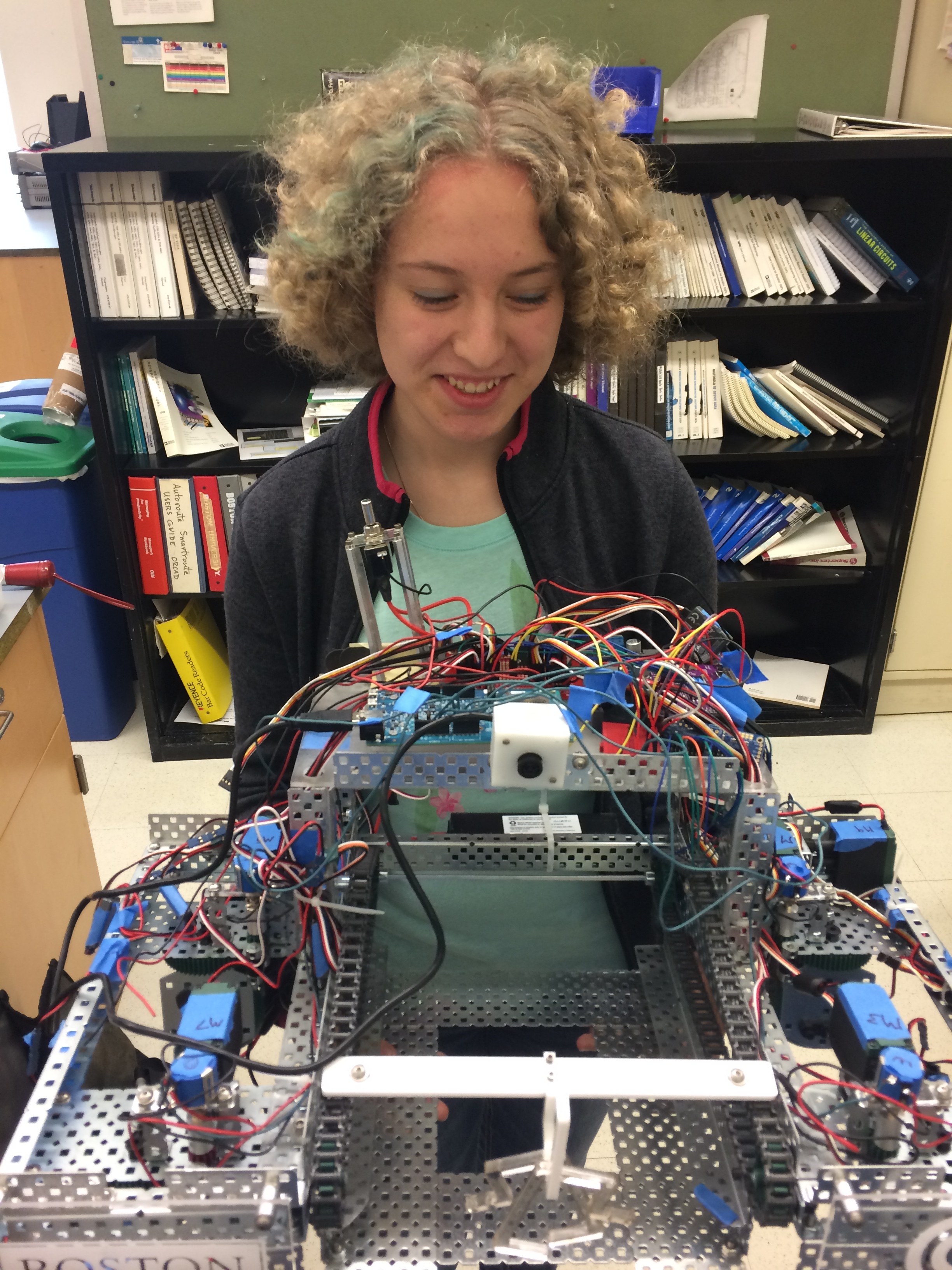
We also made some spare parts for our robot on the lasercutter, as we are taking it to ConEdison on Tuesday to present to them and we want to make sure it works! 

$\setCounter{0}$
In Personal Projects, Illusionist's Locket, Machining Projects Tags Machining
Comment
 Always use vector image formats (PNG, TIF, etc.) to ensure crisp resolution at any scale.

Always use vector image formats (PNG, TIF, etc.) to ensure crisp resolution at any scale.

 Aluminum standoff spacers

Aluminum standoff spacers

 They have an additional function to prevent the swerve modules from crashing into the plaque when the robot steers...

They have an additional function to prevent the swerve modules from crashing into the plaque when the robot steers...

 BreakerBot looking good! We have to do something about its hair though

BreakerBot looking good! We have to do something about its hair though

 Always use vector image formats (PNG, TIF, etc.) to ensure crisp resolution at any scale.  Aluminum standoff spacers  They have an additional function to prevent the swerve modules from crashing into the plaque when the robot steers...  BreakerBot looking good! We have to do something about its hair though

BreakerBot Gets a New Look

May 11, 2016

Even though our senior design class is technically over, we still have some things to finish with our project. We are traveling to my hometown of New York City to give a presentation and demonstration of our robot at ConEd. The goal of this is to convince them to continue future phases of the project at BU to design and build a full scale version of the robot. 

We spent the day trying to make our robot look a bit more professional and presentable by adding lasercut acrylic plaques of our sponsors' logos. We also turned some aluminum standoff spacers that I think add a really nice touch.

$\setCounter{0}$
In Academic Projects, BreakerBot, Machining Projects Tags BreakerBot, Lasercutting, Machining
Comment
 Spot drilling the hole

Spot drilling the hole

 Setting the 15 deg angle

Setting the 15 deg angle

 Setting the height of the cut

Setting the height of the cut

 I dimensioned the part based on how it would be fixed to make setting the height and depth easier

I dimensioned the part based on how it would be fixed to make setting the height and depth easier

 Making sure the fixture for the milling cutter wont crash into the work

Making sure the fixture for the milling cutter wont crash into the work

 Punching through some card stock

Punching through some card stock

 I should have made the punch longer as the circle gets stuck in the die

I should have made the punch longer as the circle gets stuck in the die

 It's a clean cut at least. I used a pencil to get it out

It's a clean cut at least. I used a pencil to get it out

 The finished piece with the drawing

The finished piece with the drawing

 Spot drilling the hole  Setting the 15 deg angle  Setting the height of the cut  I dimensioned the part based on how it would be fixed to make setting the height and depth easier  Making sure the fixture for the milling cutter wont crash into the work  Punching through some card stock  I should have made the punch longer as the circle gets stuck in the die  It's a clean cut at least. I used a pencil to get it out  The finished piece with the drawing

Illusionist's Heart Locket Pt. 6

May 10, 2016

Today I made another piece for the Illusionist's Heart Locket. Now that classes are over I have free time to work on personal projects, which is a relaxing way to end the school year. The purpose of this piece is to punch the pictures that will go into the locket at the correct size. A regular hole punch can't be used as it is much too small. Instead I made a custom hole punch to get the correct size photo.


The Die

The die is a block of 6061 aluminum with a hole drilled and reamed to .376" and a slot cut with a slitting saw at a 15 degree angle. The angle allows the punch to cut through the paper gradually rather than all at once, reducing the force required by the user. 


The Punch

The punch is a cylindrical piece of tool steel turned to .375" on one side and .50" on the other. The .375" side cuts the photo, while the other side is larger to stop the punch from going all the way through and also for the user to grip. Now that I know this works, I can harden the steel. The sharp edge from turning is already starting to degrade even though I've only been cutting paper...

$\setCounter{0}$
In Personal Projects, Machining Projects, Illusionist's Locket Tags Machining
Comment
 The finished mold

The finished mold

 Materials

Materials

 I used hot glue to seal the mold cavity

I used hot glue to seal the mold cavity

 Mixing the media

Mixing the media

 Pouring into the cavity

Pouring into the cavity

 Now we wait...

Now we wait...

 The finished mold  Materials  I used hot glue to seal the mold cavity  Mixing the media  Pouring into the cavity  Now we wait...

Quantum Dot Lite Brite Pt.3

April 22, 2016

The other day I was able to cast the silicone molding media to make the mold for the QD embedded plastic pieces. The molding media I bought doesn't require a vacuum as I previously thought, so I was able to cast it at home in my kitchen. It is very simple to do as it is simply a 1:1 volumetric ratio. I borrowed some multipurpose mold release from out school's "Tinker" lab, and it seemed to work just fine.

$\setCounter{0}$
In Engineering Education, Machining Projects Tags Molding, Casting, Quantum Dots
Comment
 Ready to cast the mold media. Just need some mold release.

Ready to cast the mold media. Just need some mold release.

 Gluing the box that will become the mold cavity.

Gluing the box that will become the mold cavity.

 Milling the positive from aluminum.

Milling the positive from aluminum.

 Ready to cast the mold media. Just need some mold release.  Gluing the box that will become the mold cavity.  Milling the positive from aluminum.

Quantum Dot Lite Brite Pt. 2

April 15, 2016

The specs for this design have been developed. Recently I've been working on making the molds to cast the QD plastic in. I purchased a tin-cure silicone molding media which meets the temperature requirements of the vacuum oven the plastic will be cured in. I selected tin cure over platinum cure because we have access to a vacuum chamber to de-gas the molding media as it cures, and it's a bit cheaper than the platinum cure. It also works with a wider variety of materials. The library life is not as long as the platinum cure, but that is not really a concern for this application.

I milled the positive for the mold out of aluminum. I then lasercut some acrylic to form a cavity around the positive in which to cast the mold media which will become the negative. The result will be a simple open faced mold. If the results from this mold are no good, we may try a 2 part mold, but I think a 2 part mold would be overkill for this part. 

Up Next:

  1. I have a design for the box, but I need to make sure it can be made with an efficient use of materials, and easy to assemble, as we will be making many of these devices.

  2. I need to further embody the electrical design by selecting a UV source. I am having trouble designing a UV LED array that meets the light intensity requirements to activate the QDs while being at a reasonable cost. The UV LEDs are quite expensive, and I'd need a lot of them. I'm considering reverting to a fluorescent source if it turns out to be cheaper.

$\setCounter{0}$
In Engineering Education, Machining Projects Tags Quantum Dots, Design, Molding, Casting, Machining, CNC
Comment
 Checking the dimension of the pin head. Right on the money.

Checking the dimension of the pin head. Right on the money.

 The completed pin.

The completed pin.

IMG_7234.jpg
 Measurements of the corner rounding tool for GibbsCAM.

Measurements of the corner rounding tool for GibbsCAM.

 Testing the corner rounding operation on aluminum. It came out pretty well!

Testing the corner rounding operation on aluminum. It came out pretty well!

 Testing the barrel hole drilling operation.

Testing the barrel hole drilling operation.

 Reaming the hole.

Reaming the hole.

 Chamfering the hole.

Chamfering the hole.

 The barrel hole, complete. Much better finish than with the ball mill.

The barrel hole, complete. Much better finish than with the ball mill.

IMG_7248.jpg
IMG_7252.jpg
 Counterbored hole for the head of the pin.

Counterbored hole for the head of the pin.

 You can see a slight step from the corner rounding tool. I kind of like the way it looks though.

You can see a slight step from the corner rounding tool. I kind of like the way it looks though.

IMG_7263.jpg
 Turning the tapered barrel to match the twist drill angle. But I got the angle wrong...

Turning the tapered barrel to match the twist drill angle. But I got the angle wrong...

 Ready to machine the final product with copper. 

Ready to machine the final product with copper. 

IMG_7266.jpg
 The results! Along with all the other various prototypes I made.

The results! Along with all the other various prototypes I made.

 Checking the dimension of the pin head. Right on the money.  The completed pin. IMG_7234.jpg  Measurements of the corner rounding tool for GibbsCAM.  Testing the corner rounding operation on aluminum. It came out pretty well!  Testing the barrel hole drilling operation.  Reaming the hole.  Chamfering the hole.  The barrel hole, complete. Much better finish than with the ball mill. IMG_7248.jpg IMG_7252.jpg  Counterbored hole for the head of the pin.  You can see a slight step from the corner rounding tool. I kind of like the way it looks though. IMG_7263.jpg  Turning the tapered barrel to match the twist drill angle. But I got the angle wrong...  Ready to machine the final product with copper.  IMG_7266.jpg  The results! Along with all the other various prototypes I made.

Illusionist's Locket Pt. 5

March 19, 2016

Quick update or my locket project. The pin is complete, and to spec. I decided to try using a corner rounding tool to give the locket more refined appearance. They are notoriously difficult to setup in the CNC machine, so I did a test run on a plastic part and on 2 aluminum parts to make sure I got it right before machining into my expensive copper. I also tested the drilling operations on the barrel hole. I originally made this feature with a ballnose mill on the CNC, but the finish was very poor and I would have to ream it anyway to improve the finish. So I decided I might as well drill and ream it from the get-go. 

To do this, I simply clamped two pieces together in the vice, using a parallel bar over the top of the vice to keep the faces normal to the axis of the mill spindle. Then I used an edge finder to locate the hole locations and drilled, reamed and countersunk the holes. 

After confirming all of these things could be done, I decided I was ready to begin making the final product from my copper plate. The feeds and speeds for copper are very slow, and it took almost 2 hours just to make these four little parts. The quality of two of the parts was acceptable, however the other two had gouges in them from the .25" end mill. I think that it was caused by two of the parts being mirrors of the other. For some reason, when coming around the parts the other way, the end mill got sucked into the part, causing those gouges. I may need to remake two of those parts. 

$\setCounter{0}$
In Personal Projects, Illusionist's Locket, Machining Projects Tags Machining, CNC
2 Comments
image7.jpeg
image6.jpeg
image5.jpeg
image3.jpeg
image2.jpeg
image1.jpeg
image7.jpeg image6.jpeg image5.jpeg image3.jpeg image2.jpeg image1.jpeg

Illusionist's Locket Pt. 4

March 14, 2016

I did some work on the locket today. The first thing I did was I marked the sides of the magnets with a sharpie so I could distinguish between the N and S poles. To do this, I just stacked them all up and sharpie-d the tops one by one. 

The next thing I did was I heat treated a pin I turned from O1 tool steel. I used the furnace to gradually heat it to 1450F and let it soak for 15min. I then quenched it in oil. The subsequent hardness test shows a hardness of almost C59 Rockwell. It started out as B96. The spec sheet says it can be hardened up to C64, but I am satisfied with C59. This just means I don't have to temper it back down again. Next I'm going to turn down the diameter a bit more with a tungsten-carbide tool and finish it with a grindstone on the lathe. I would use a cylindrical grinding method, but we don't really have that capability at the shop. 

$\setCounter{0}$
In Personal Projects, Illusionist's Locket, Machining Projects Tags Machining, Materials, Heat Treatment
Comment
IMG_7091.jpg
IMG_7089.jpg
IMG_7090.jpg
IMG_7086.jpg
IMG_7087.jpg
IMG_7088.jpg
IMG_7091.jpg IMG_7089.jpg IMG_7090.jpg IMG_7086.jpg IMG_7087.jpg IMG_7088.jpg

A Hard Day's Work

February 22, 2016

I love working with my hands and making things. At the end of the day, I find it very satisfying to be able to look at the things I've made and say "this is what I did today".

What I did:

  1. Finished assembling the scaled circuit breaker model for our senior design project. This involved gluing up the sides of the box, and screwing on the wheels and the rollers. We did not have a thin enough wrench to tighten the roller between the two surfaces, so I had to make one.

  2. Began prototyping the device to reduce torsion in coils of optical fibers. I used the laser cutter with 1/4" acrylic. I designed the part so that I could prototype it in 1/4" layers, stacking and gluing together different profiles to get the correct geometry of the final part. The part on the bottom is composed of just two layers. The part on the top (with the spiraling slots) is a single layer part.

$\setCounter{0}$
In BreakerBot, Personal Projects, Machining Projects Tags Lasercutting, Machining
Comment
IMG_7073.jpg
IMG_7074.jpg
IMG_7075.jpg
IMG_7076.jpg
IMG_7073.jpg IMG_7074.jpg IMG_7075.jpg IMG_7076.jpg

Illusionist's Locket Pt. 3

February 16, 2016

I machined the first parts of a prototype today. I used a 3/8" ball-mill to get the central channel for the barrel pivot to rest in. I'm trying to see if there is a better way to do this, as the ballmill leaves a circular edge when I'd rather have a flat face. Also, slight errors in the depth of the ballmill correspond to the channel for the barrel not being cylindrical. There are still many improvements to be made!

$\setCounter{0}$
In Personal Projects, Illusionist's Locket, Machining Projects Tags CNC, Machining, SolidWorks
Comment
 Oval configuration: red barrel visible.

Oval configuration: red barrel visible.

 Heart configuration: green barrel visible.

Heart configuration: green barrel visible.

 Here you can see how the barrels move when you rotate the mechanism from the oval to the heart or vice versa.

Here you can see how the barrels move when you rotate the mechanism from the oval to the heart or vice versa.

 Mystery solved! There's no magic here.

Mystery solved! There's no magic here.

image5.png
 Oval configuration: red barrel visible.  Heart configuration: green barrel visible.  Here you can see how the barrels move when you rotate the mechanism from the oval to the heart or vice versa.  Mystery solved! There's no magic here. image5.png

Illusionist's Locket Pt. 2

February 11, 2016

Today I was able to reverse engineer the mechanism that switches the photos in the locket depending on the configuration. The key is having a two-part barrel that the halves pivot about. The two parts of the barrel are not attached, allowing them to separate when the locket is opened. Each half of the barrel is fixed to one of the movable heart pieces, allowing the other heart pieces to rotate around them, and allowing the barrel halves to slide over each other. 

The next step is to incorporate this mechanism into my existing design. I will probably need a few more magnets to hold the locket closed. I will also modify some of the geometry of the barrels and the barrel slots so they are machinable. 

$\setCounter{0}$
In Personal Projects, Machining Projects, Illusionist's Locket Tags Design, Mechanisms, Reverse Engineering, CAD, SolidWorks
Comment
 Heart configuration. Magnets are attracted to each other, so the configuration is stable.

Heart configuration. Magnets are attracted to each other, so the configuration is stable.

 Rotating the two halves

Rotating the two halves

 Oval configuration. Magnets now repel each other, so the two halves can easily be pulled apart,

Oval configuration. Magnets now repel each other, so the two halves can easily be pulled apart,

 Disassembly of the two halves reveals hidden pocket for a ring, note, etc.

Disassembly of the two halves reveals hidden pocket for a ring, note, etc.

 "MD" Side

"MD" Side

 "DM" Side

"DM" Side

 In the oval configuration.

In the oval configuration.

 Heart configuration. Magnets are attracted to each other, so the configuration is stable.  Rotating the two halves  Oval configuration. Magnets now repel each other, so the two halves can easily be pulled apart,  Disassembly of the two halves reveals hidden pocket for a ring, note, etc.  "MD" Side  "DM" Side  In the oval configuration.

Illusionist's Locket

February 9, 2016

This is a present I plan on making for my girlfriend for Valentine's Day. It is a metal heart made of two halves that are connected with a dowel pin and magnets. When the two halves are arranged in the heart configuration, the magnets attract each other and so the configuration is stable. When you twist the halves apart, the halves take the form of an oval. With the magnets' positions switched, the halves repel each other, allowing the user to separate the halves and gain access to the secret pockets inside each half. The secret pockets can be used to small rings, a small note, etc.

I've also decided to take advantage of the fact that our initials form a palindrome. If our initials are engraved a certain way on the two halves, on one side of the heart configuration the letters read "MD" (her initials) and on the other side the initials read "DM" (my initials). When rotated to the oval configuration, both sides are the same but are upside down relative to each other. So it reads "DM" or "MD" depending on how you look at it. I like to think of it as being symbolic of our partnership together.

Manufacturing should be relatively simple. The two halves can be CNC'd out of bar stock. I made the angle on each half 45 deg so that any standard shop gauge block could be used to mount the middle face parallel to the table of the mill for drilling the holes and milling the slot. I plan to use a 1/8" steel dowel pin for the center pivot shaft which can be turned on the lathe. Adhesive backed neodymium magnets will be used for retention. If I decide to do the engraving I will need to make some sort of fixture or jig for a flip milling operation on the reverse side of each half of the heart. Hopefully I can make a simple jig with some locating pins mounted on the mill table.

Note: This design is inspired by an Instructable I remembered seeing a while back. The author of the Instructable credits the design to a scene from the movie "The Illusionist". As you can see, the locket in the movie has 2 additional hinges that allow the locket to swing open in both the oval and heart configuration. The "illusion" is that when you open the locket in one configuration, one person's image appears. But when you open the locket in the other configuration, the other person's image appears. And the baffling thing is, it's hard to understand how twisting the locket from the heart to the oval configuration doesn't rip the picture in half. This is a *greatly* simplified version where there really is no illusion. I will use this design as a starting point and hopefully be able to design a locket that has the full functionality as seen in the movie.

$\setCounter{0}$
In Personal Projects, Illusionist's Locket, Machining Projects Tags Machining, CNC, SolidWorks, CAD
Comment
 I missed some photos in the beginning. These are the two jaws of the vise being faced off with a flycutter while bolted together. This was to ensure that the surfaces were parallel and coincident. 

I missed some photos in the beginning. These are the two jaws of the vise being faced off with a flycutter while bolted together. This was to ensure that the surfaces were parallel and coincident. 

 I also had to cut stepper blocks to a certain size in order to ensure the vice clamped the center of the rods.

I also had to cut stepper blocks to a certain size in order to ensure the vice clamped the center of the rods.

 This shows the initial setup. The vise is on the stepper blocks, and parallels are used to ensure the rods are vertical. 

This shows the initial setup. The vise is on the stepper blocks, and parallels are used to ensure the rods are vertical. 

 After tightening the bolts of the vise, I realized the vise was only gripping the two largest dowels. So I cut a piece of rubber to fit in between one of the vise jaws and the dowels to better distribute the pressure amongst the dowels. 

After tightening the bolts of the vise, I realized the vise was only gripping the two largest dowels. So I cut a piece of rubber to fit in between one of the vise jaws and the dowels to better distribute the pressure amongst the dowels. 

IMG_6001.jpg
 The first machining test. You can see the tops of the rods were clamped together using parallels. This helped a lot to reduce the variability. 

The first machining test. You can see the tops of the rods were clamped together using parallels. This helped a lot to reduce the variability. 

 I used even taller parallels the second time, to reduce the variability more. This run had pretty consistent results. I just wish we had an endmill that was smaller than 1/8". 

I used even taller parallels the second time, to reduce the variability more. This run had pretty consistent results. I just wish we had an endmill that was smaller than 1/8". 

 I missed some photos in the beginning. These are the two jaws of the vise being faced off with a flycutter while bolted together. This was to ensure that the surfaces were parallel and coincident.   I also had to cut stepper blocks to a certain size in order to ensure the vice clamped the center of the rods.  This shows the initial setup. The vise is on the stepper blocks, and parallels are used to ensure the rods are vertical.   After tightening the bolts of the vise, I realized the vise was only gripping the two largest dowels. So I cut a piece of rubber to fit in between one of the vise jaws and the dowels to better distribute the pressure amongst the dowels.  IMG_6001.jpg  The first machining test. You can see the tops of the rods were clamped together using parallels. This helped a lot to reduce the variability.   I used even taller parallels the second time, to reduce the variability more. This run had pretty consistent results. I just wish we had an endmill that was smaller than 1/8". 

Mini Project: Tooling/Fixturing for Tensegrity Rods

February 3, 2015

Part of my job as an engineering education developer includes designing and manufacturing the parts needed for the activities. One of the activities I helped create was on the structural design principle of tensegrity. Tensegrity is a way to build structures that are lightweight and strong. They rely on flexible tensile elements such as strings, ropes, or cables; as well as on stiff compressional elements such as rods. Tensegrity structures are pre-stressed and self stabilizing, and none of the compressional members touch. They are suspended in a web of tensional elements, a phenomenon referred to as "floating compression" by artist Kenneth Snelson. 

The activity itself is like a board game to teach students the entrepreneurial aspects of engineering. The activity centers around building a mini tensegrity tower. These towers use wooden dowels with notches cut in either end; rubber bands fit in these notches and hold the rods together in a simple tensegrity structure. The problem is that the balance and symmetry of the tower depends on the quality of the rods. All the rods must be made to a high standard, or else the tensegrity towers become very asymmetrical and unstable. This is because with different length rods, the rubber bands are stretched to different lengths and therefore exert different restoring forces. The imbalance of restorative forces within the structure causes the structure to shift in order to find a new equilibrium. This throws everything off. 

To make the towers as balanced as possible, a manufacturing method was needed to produce the rods very quickly and precisely. I decided to make a simple vise to hold the rods. The vise is clamped into the vise of a mill, which can be used to machine the notches on one end. Then, the inner vise can be flipped upside down to machine the other side of the rods. 

There were a few caveats to this approach; the length of the rods compared to the size of the vise made it difficult to clamp into the mill's vise jaws. Additionally, the length of the dowels sticking out of the vise made it difficult to machine cleanly without using extra clamps to restrict the motion. All in all, however, it worked pretty well and I think these towers will perform much better.

$\setCounter{0}$
In Engineering Education, Machining Projects
Comment
 Original sketch of concept

Original sketch of concept

 More detailed sketches of the parts. I ended up changing most of the dimensions.

More detailed sketches of the parts. I ended up changing most of the dimensions.

 Open Position

Open Position

 Closed Position

Closed Position

 30˚!

30˚!

 Threads won't go that deep in the hole... Gotta make the hole deeper.

Threads won't go that deep in the hole... Gotta make the hole deeper.

 Original sketch of concept  More detailed sketches of the parts. I ended up changing most of the dimensions.  Open Position  Closed Position  30˚!  Threads won't go that deep in the hole... Gotta make the hole deeper.

Project: Drafting Bars

January 20, 2015

Engineers convey ideas through drawings and sketches. When sketching rectangular objects in orthographic or isometric views, it is necessary to be able to draw parallel lines. Additionally, for isometric views, the lines are offset 30˚ from the horizontal. I wanted to make a tool that would help me draw parallel lines and 30˚ angles to be able to make sketches quicker and more accurately.

My initial conceptual idea was to have two bars connected by two rods to form a parallelogram linkage. This way, one bar could 'follow' the original line, while the other [parallel] bar could be extended and a parallel line could be traced along the edge of the bar at any desired distance. 

Making the 30˚ angle was more tricky. My original thought was to have different sized rods that could be swapped out to make different angles, but I thought there was probably a simpler and more elegant way to do it. I eventually decided to add extra holes as alternate positions for the rods. In their alternate positions the rods are no longer parallel, and thus the angle between the bars can change. The freedom of motion of the bars is limited by their interference, and so by adjusting the geometries of the parts, a 30˚ can be obtained when the bars are touching each other. 

The last element of the design was how all the pieces fit together. I decided to use knurled brass knobs that threaded into a nut. The nut head fits into a channel, and the shank of the nut slides in a slot. The rod end fits around the nut, and the length of the rod is contained within a pocket in the bar. Tightening the knob presses the bar against the rod to lock it in place. If the knob is unscrewed completely, the rod end can be moved to a different hole to get the 30˚ angle.

This is the first version of the design. I'm still not sure what materials to use for the different parts. I really like the look of knurled brass knobs and rods, but I'll need to make sure they are strong enough. I originally planned to use 304 Stainless Steel for the bars for longevity and cost, but the locking function depends on the the ability of the bar to deflect under the force of the knob and press against the rod. 


$\setCounter{0}$
In Personal Projects, Machining Projects Tags Machining
Comment

Blogpost Search

Blogposts by Category

Select Category
  • Academic Projects
  • Aviation
  • BreakerBot
  • Engineering Education
  • Illusionist's Locket
  • MATLAB Projects
  • Machining Projects
  • Personal Projects

Archive

  • May 2024
  • December 2019
  • November 2019
  • September 2019
  • April 2017
  • January 2017
  • August 2016
  • May 2016
  • April 2016
  • March 2016
  • February 2016
  • January 2016
  • November 2015
  • October 2015
  • June 2015
  • April 2015
  • February 2015
  • January 2015

Copyright © David Miller 2019