• Portfolio
  • Aviation
  • Blog
  • About
Menu

David S Miller

  • Portfolio
  • Aviation
  • Blog
  • About
 It appears that this mechanism is valid... But how can I be sure?

It appears that this mechanism is valid... But how can I be sure?

 By plotting arcs around the links I ensure they stay the same size throughout.

By plotting arcs around the links I ensure they stay the same size throughout.

 Here are some varying geometries that achieve the same goal.

Here are some varying geometries that achieve the same goal.

 This is when I was still debugging my code. You can clearly see each member changes length as it rotates, which cannot occur.

This is when I was still debugging my code. You can clearly see each member changes length as it rotates, which cannot occur.

 This geometry resulted in a bearing that was placed off the surface of the shipping container.

This geometry resulted in a bearing that was placed off the surface of the shipping container.

 One more geometry. The next question is, how can you optimize the linkage??

One more geometry. The next question is, how can you optimize the linkage??

 I tried plotting snapshots of the linkage but it didn't work so well. This is wrong because the magenta snapshots do not align with the red position.

I tried plotting snapshots of the linkage but it didn't work so well. This is wrong because the magenta snapshots do not align with the red position.

 It appears that this mechanism is valid... But how can I be sure?  By plotting arcs around the links I ensure they stay the same size throughout.  Here are some varying geometries that achieve the same goal.  This is when I was still debugging my code. You can clearly see each member changes length as it rotates, which cannot occur.  This geometry resulted in a bearing that was placed off the surface of the shipping container.  One more geometry. The next question is, how can you optimize the linkage??  I tried plotting snapshots of the linkage but it didn't work so well. This is wrong because the magenta snapshots do not align with the red position.

MATLAB Four-Bar Linkage Design

March 24, 2016

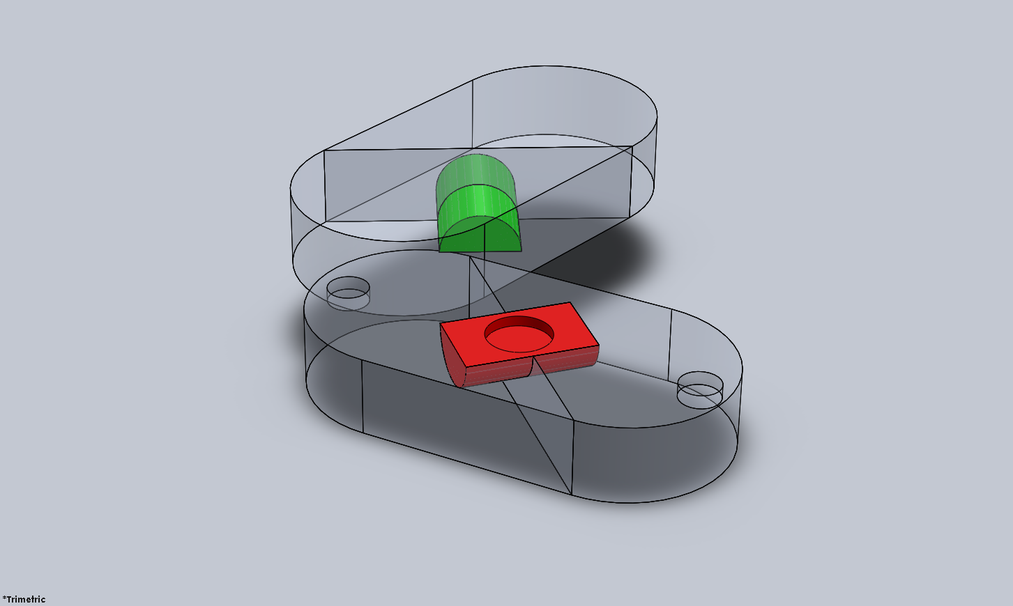
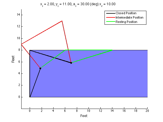
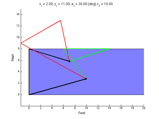
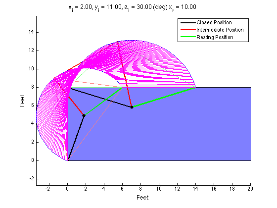
The Product Design class I am a TA for had an assignment to design a four-bar mechanism to move a lid on a shipping container up and over so that it rested on the top of the container during loading. There was extra credit awarded to those who could analytically arrive at a design using MATLAB (or some other language). I made my own solution for fun and to check student's solutions. I tried to get it to plot each snapshot (in magenta) but it was not correct and I didn't have time to figure it out. 

So, here's how to design a typical four-bar linkage:

  1. Define the desired locations of your coupler. You define two or three locations you want the coupler to travel through. My code only works with three locations.

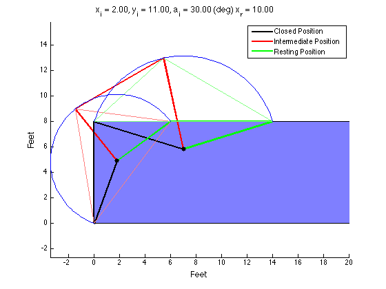
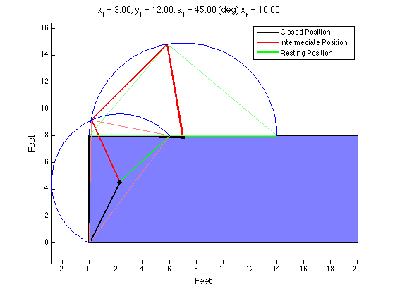
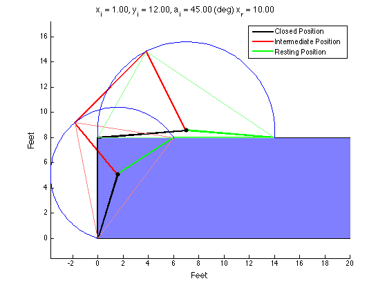
  2. Find the locus of points that is equidistant from where the crank connects to the coupler in each position. If two coupler positions are defined, the locus will be an infinite line (think of the intersection of two circles; connecting the two points forms a line). If three coupler positions are defined, the locus collapses to a single point. This point also happens to be the circumcenter of the triangle formed by the three vertices the bearing must be equidistant from. The bearing must be placed on a point on the locus. If the locus is a single point, your job is done. If the locus is a line, you must select a point on that line to be your bearing location.

  3. Repeat step 2 for the points where the rocker connects to the coupler.

  4. Once you have the bearing locations for the crank and the rocker, you can easily calculate the lengths of each link.

$\setCounter{0}$
In Academic Projects, Personal Projects, MATLAB Projects Tags MATLAB, kinematics, Mechanisms
Comment
iso_perpective_render.JPG
iso_exp_perpective_render.JPG
 Opening

Opening

 Exposed Control Rods

Exposed Control Rods

iso_perpective_render.JPG iso_exp_perpective_render.JPG  Opening  Exposed Control Rods

Isolating Pure Bending in Optical Fibers

February 20, 2016

One of the grad students from the nanophotonics lab I developed the microbend apparatus for contacted me regarding a question he had. He was trying to isolate bending and torsional loads in optical fibers to investigate their effects. Introducing pure bending in a fiber is difficult because the fibers have very little torsional stiffness. It's easy to eliminate bends to a twisted fiber by simply adding a bit of tension to the ends. But how do you eliminate twist? There is so little stiffness that you cannot rely on the restoring torque to eliminate small twists in the fiber. The current solution is to coil the fiber very loosely (coiling is just one very long continuous bend) whatever twist is inadvertently introduced by the act of coiling will distribute itself along the length of the entire fiber. In contrast, in fiber optic gyroscope winding, because the coils are so tight, the minor twists in the fiber get trapped between turns of the coil, leaving behind localized residual torsions in the fiber. 

The downside to a loose coil is that it is very hard to get each turn in the coil to the same diameter. A constant bending radius is required for accurate measurements. We decided to use an iris diaphragm mechanism to control the diameter of 6 pins, which the fiber will loosely be wrapped around as guides. This way, a very minimal amount of tension could be used to make sure the coils are all the same diameter, and the diameter can be adjusted using the iris mechanism. To go along with this, it would be helpful to have a limited slip fiber clamp and constant force spring loaded spool so the diameter could be adjusted either direction without having to manually pick up slack in the fiber or loosen the coils to reduce the tension. 

One other alternative to this 'loose coil' solution is to actively measure and correct the fiber twist. However, this method seems overly complex. It really depends on how much twist is tolerable. Once that is quantified, we will be able to determine what type of solution is required. I have a feeling the tolerance will not be so tight as to necessitate some type of active system. But I wonder if there is a better solution for an active system? Perhaps if instead of wrapping the fiber around pins, we could wrap it around an expanding cylinder controlled by the iris mechanism. But I have no idea how that could work. Time to start brainstorming...

$\setCounter{0}$
In Personal Projects Tags Optics, Fiber, Mechanisms, kinematics, SolidWorks, Design
Comment
 Oval configuration: red barrel visible.

Oval configuration: red barrel visible.

 Heart configuration: green barrel visible.

Heart configuration: green barrel visible.

 Here you can see how the barrels move when you rotate the mechanism from the oval to the heart or vice versa.

Here you can see how the barrels move when you rotate the mechanism from the oval to the heart or vice versa.

 Mystery solved! There's no magic here.

Mystery solved! There's no magic here.

image5.png
 Oval configuration: red barrel visible.  Heart configuration: green barrel visible.  Here you can see how the barrels move when you rotate the mechanism from the oval to the heart or vice versa.  Mystery solved! There's no magic here. image5.png

Illusionist's Locket Pt. 2

February 11, 2016

Today I was able to reverse engineer the mechanism that switches the photos in the locket depending on the configuration. The key is having a two-part barrel that the halves pivot about. The two parts of the barrel are not attached, allowing them to separate when the locket is opened. Each half of the barrel is fixed to one of the movable heart pieces, allowing the other heart pieces to rotate around them, and allowing the barrel halves to slide over each other. 

The next step is to incorporate this mechanism into my existing design. I will probably need a few more magnets to hold the locket closed. I will also modify some of the geometry of the barrels and the barrel slots so they are machinable. 

$\setCounter{0}$
In Personal Projects, Machining Projects, Illusionist's Locket Tags Design, Mechanisms, Reverse Engineering, CAD, SolidWorks
Comment

Blogpost Search

Blogposts by Category

Select Category
  • Academic Projects
  • Aviation
  • BreakerBot
  • Engineering Education
  • Illusionist's Locket
  • MATLAB Projects
  • Machining Projects
  • Personal Projects

Archive

  • May 2024
  • December 2019
  • November 2019
  • September 2019
  • April 2017
  • January 2017
  • August 2016
  • May 2016
  • April 2016
  • March 2016
  • February 2016
  • January 2016
  • November 2015
  • October 2015
  • June 2015
  • April 2015
  • February 2015
  • January 2015

Copyright © David Miller 2019